
Lighting device

a technology of light-emitting diodes and lighting devices, which is applied in the direction of lighting support devices, electric lighting, lighting and heating apparatus, etc., can solve the problem of relatively small projection angle of light emitted from light-emitting diodes, and achieve the effect of enhancing the projection angle of lighting devices and enhancing the illumination of lighting devices

Inactive Publication Date: 2013-02-21
ASIA VITAL COMPONENTS SHENZHEN CO LTD
View PDF3 Cites 41 Cited by
  • Summary
  • Abstract
  • Description
  • Claims
  • Application Information

AI Technical Summary

Benefits of technology

The present invention provides a lighting device with a larger projection angle and range. The device has a substrate with multiple light-emitting elements arranged on it. By changing the configuration of the substrate, the positions of the light-emitting elements can be changed, allowing them to be arranged in different angular positions. This results in a larger projection angle, improving the illumination of the device without the need for additional optical components.

Problems solved by technology

However, the projection angle of the light emitted from the light-emitting diode is relatively small.
1. Smaller projection angle.
2. Poor permeability.
3. Smaller projection range.

Method used


Image

  • Lighting device
  • Lighting device
  • Lighting device

Examples


Embodiment Construction

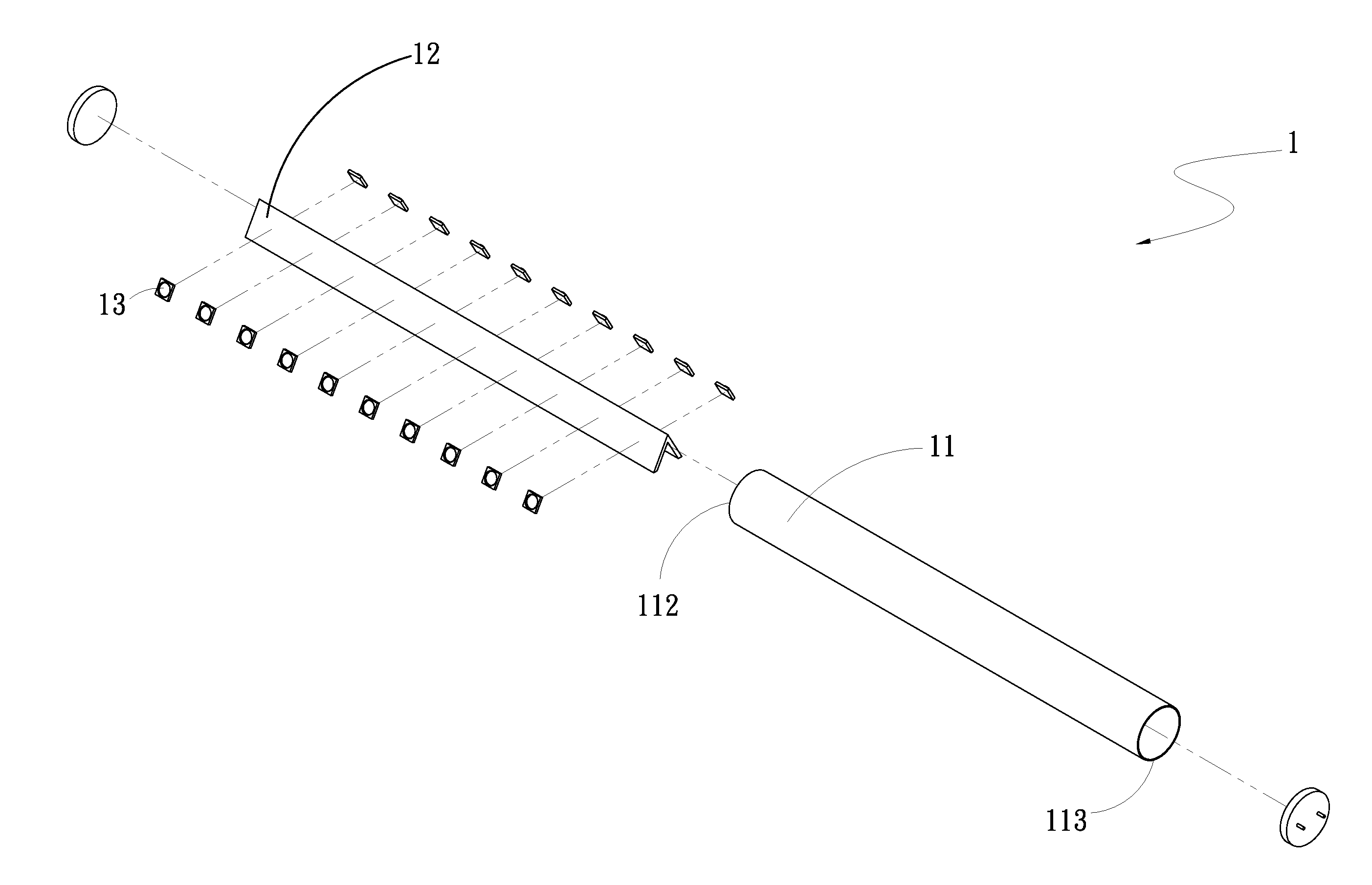
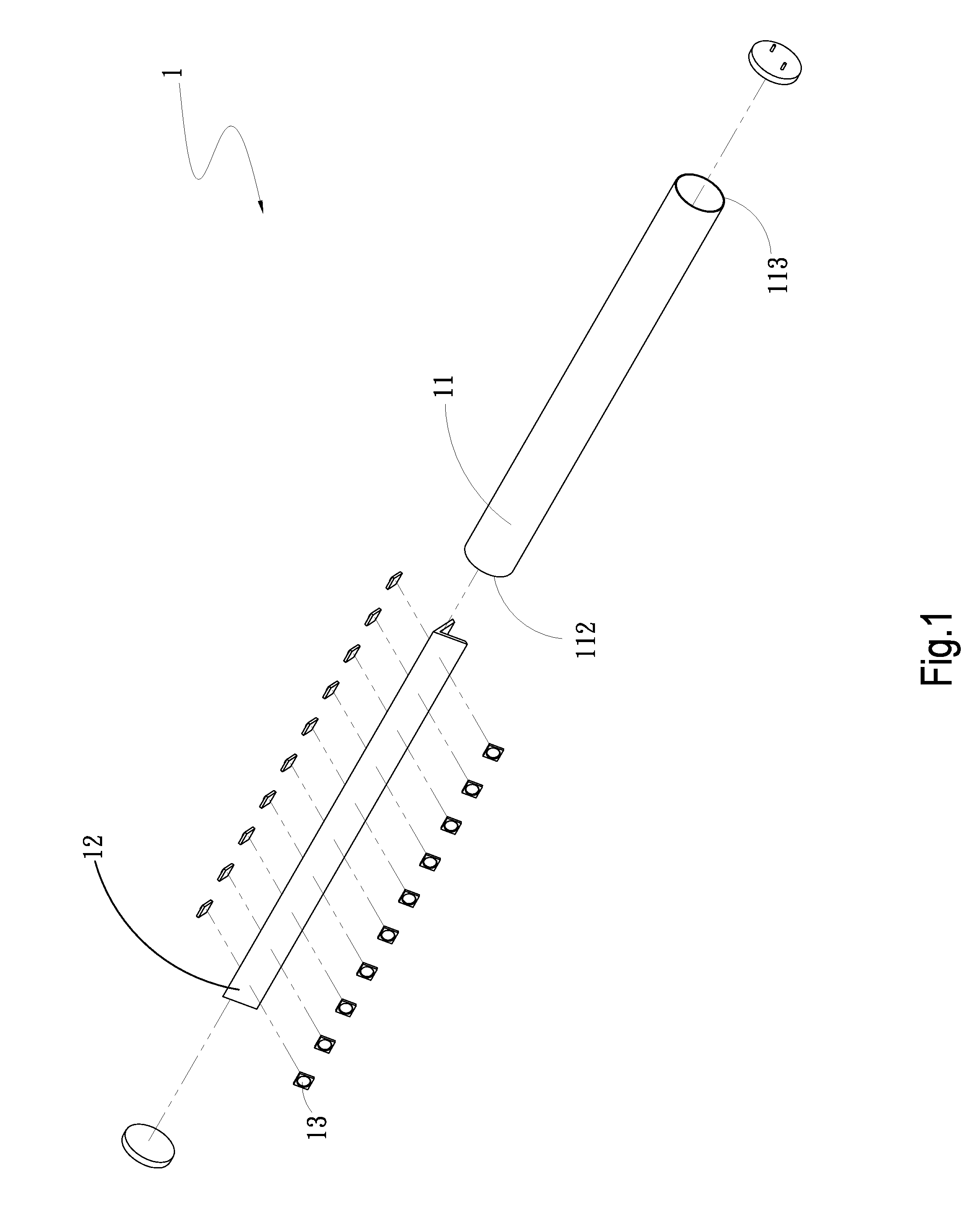
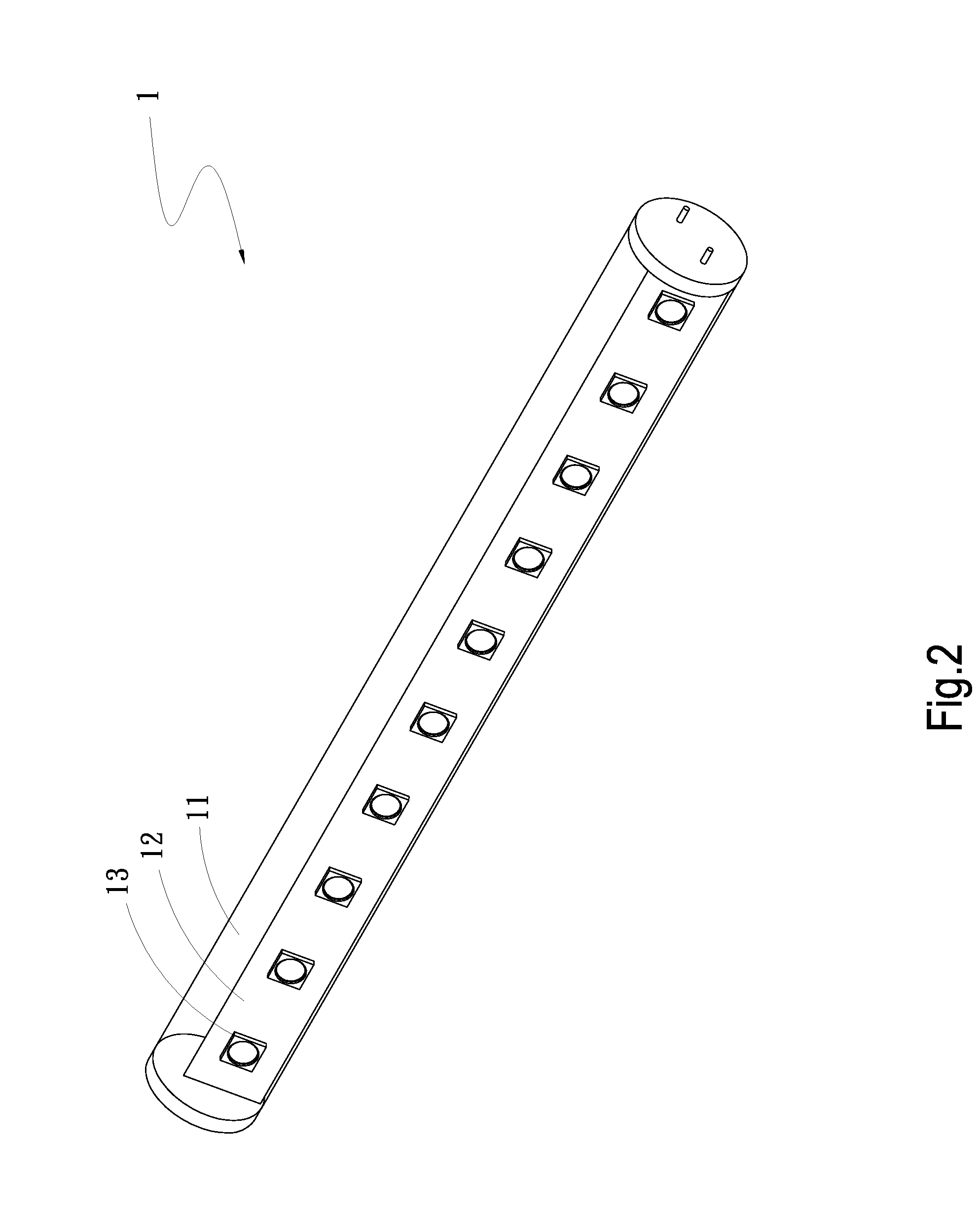
[0018]Please refer to FIGS. 1, 2 and 3. FIG. 1 is a perspective exploded view of a first embodiment of the lighting device of the present invention. FIG. 2 is a perspective assembled view of the first embodiment of the lighting device of the present invention. FIG. 3 is a sectional view of the first embodiment of the lighting device of the present invention. According to the first embodiment, the lighting device 1 of the present invention includes a tubular body 11 and a substrate 12.

[0019]The tubular body 11 has a chamber 111, a first end 112 and a second end 113. The first and second ends 112, 113 communicate with the chamber 111.

[0020]The substrate 12 is axially disposed in the chamber 111. Multiple light-emitting elements 13 are arranged on the substrate 12.

[0021]The light-emitting elements 13 are light-emitting diodes arranged on one side of the substrate 12.

[0022]The substrate 12 has a first extension section 121 and a second extension section 122. One end of the first extensi...


PUM


Abstract

A lighting device includes a tubular body and a substrate. The tubular body has a chamber, a first end and a second end. The first and second ends communicate with the chamber. The substrate is axially disposed in the chamber. Multiple light-emitting elements are arranged on the substrate. By means of the substrate, the projection range and projection angle of the lighting device are enlarged to enhance luminous efficiency of the lighting device.

Description

BACKGROUND OF THE INVENTION[0001]1. Field of the Invention[0002]The present invention relates generally to a lighting device with larger projection angle and projection range.[0003]2. Description of the Related Art[0004]There is a trend toward energy saving and carbon reduction in the field of lighting equipments. Accordingly, the conventional tungsten filament bulbs have been gradually replaced with light-emitting diodes for saving power.[0005]The light-emitting diode has the advantage of energy saving. However, the projection angle of the light emitted from the light-emitting diode is relatively small. This is because the lighting angle of the light-emitting diode is simply about 120 degrees due to its own luminous properties. Therefore, in the case that the light-emitting diode is assembled with a light tube without property of diffusion, the lighting angle of the light-emitting diode can be hardly enlarged.[0006]In many application situations, clients desire that the luminous pr...

Claims


Application Information

Patent Timeline
IPC IPC(8): F21S4/00F21V21/00
CPCF21K9/17F21Y2111/001F21K9/275F21Y2107/00F21Y2107/30F21Y2115/10F21K9/27
Inventor CHEN, TIEN-PAO
Owner ASIA VITAL COMPONENTS SHENZHEN CO LTD
Learn More