Chemical injection system

a chemical injection and system technology, applied in the direction of valve operating means/release devices, wellbore/well accessories, sealing/packing, etc., can solve the problems of wasting expensive specialty chemicals or fluids, affecting the performance of the system, and affecting the quality of the system

Inactive Publication Date: 2013-02-28
SCHLUMBERGER TECH CORP
View PDF6 Cites 31 Cited by
  • Summary
  • Abstract
  • Description
  • Claims
  • Application Information

AI Technical Summary

Benefits of technology

[0003]In general, the present disclosure provides a system and method for controlling fluid flows, such as fluid flows in a downhole well zone or zones. A flow control valve is employed to control a fluid flow and is operationally linked with an injection valve, e.g. a chemical injection valve. Actuation of the flow control valve is used to automatically actuate the injection valve between corresponding positions allowing or blocking fluid injection to the associated zone.

Problems solved by technology

The chemical injection is generally continuous and non-selective, i.e. the amount of injected fluid into a specific zone cannot easily be varied over time and in relation to other injection points in the well.
Sometimes injected chemicals can build up in an isolated zone and are potentially damaging to the reservoir and associated completion equipment due to the increasing concentration of foreign chemical constituents.
Over-injection also represents a potentially wasteful use of costly specialty chemicals or fluids

Method used


Image

  • Chemical injection system
  • Chemical injection system
  • Chemical injection system

Examples


Embodiment Construction

[0011]In the following description, numerous details are set forth to provide an understanding of some embodiments of the present disclosure. However, it will be understood by those of ordinary skill in the art that the system and / or methodology may be practiced without these details and that numerous variations or modifications from the described embodiments may be possible.

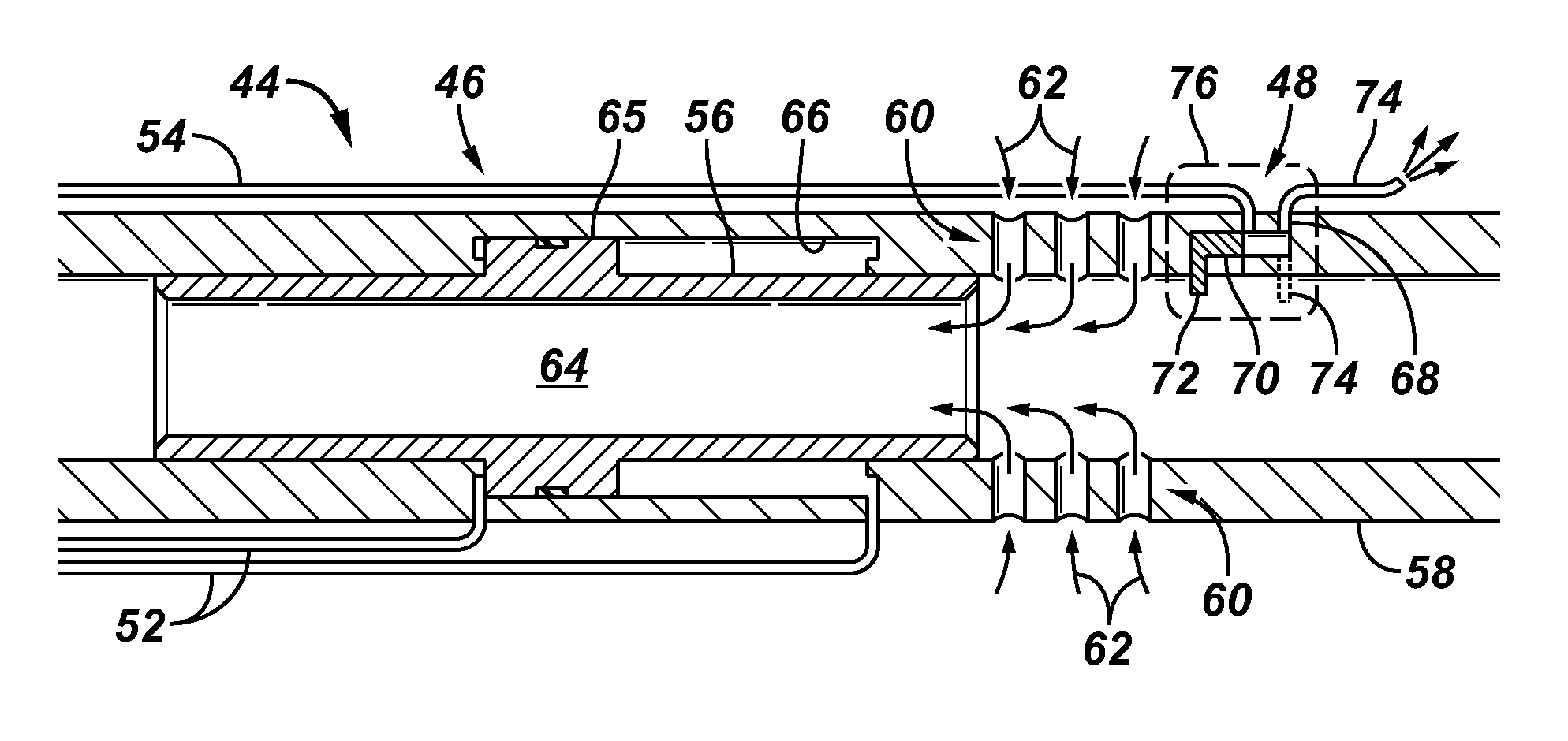
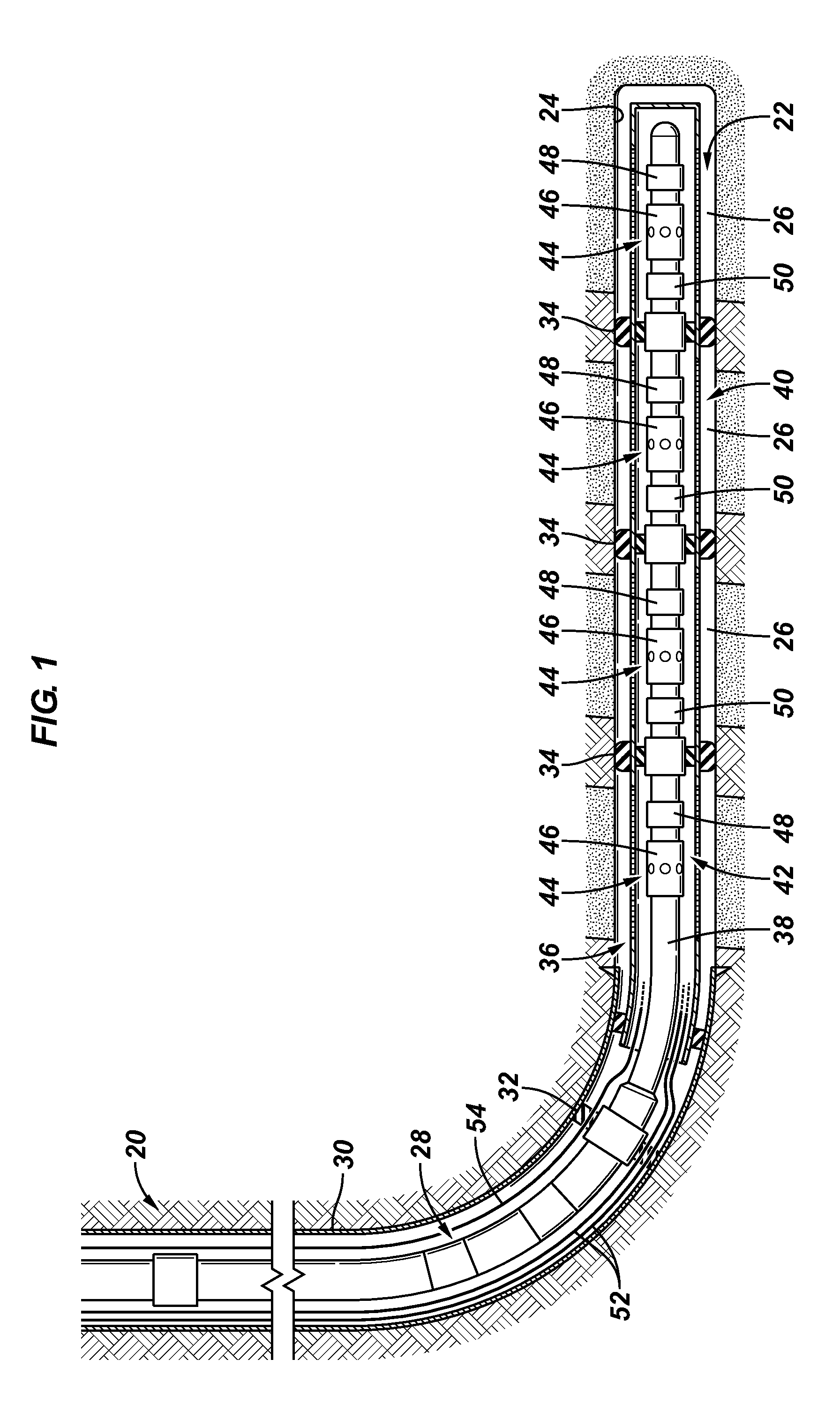
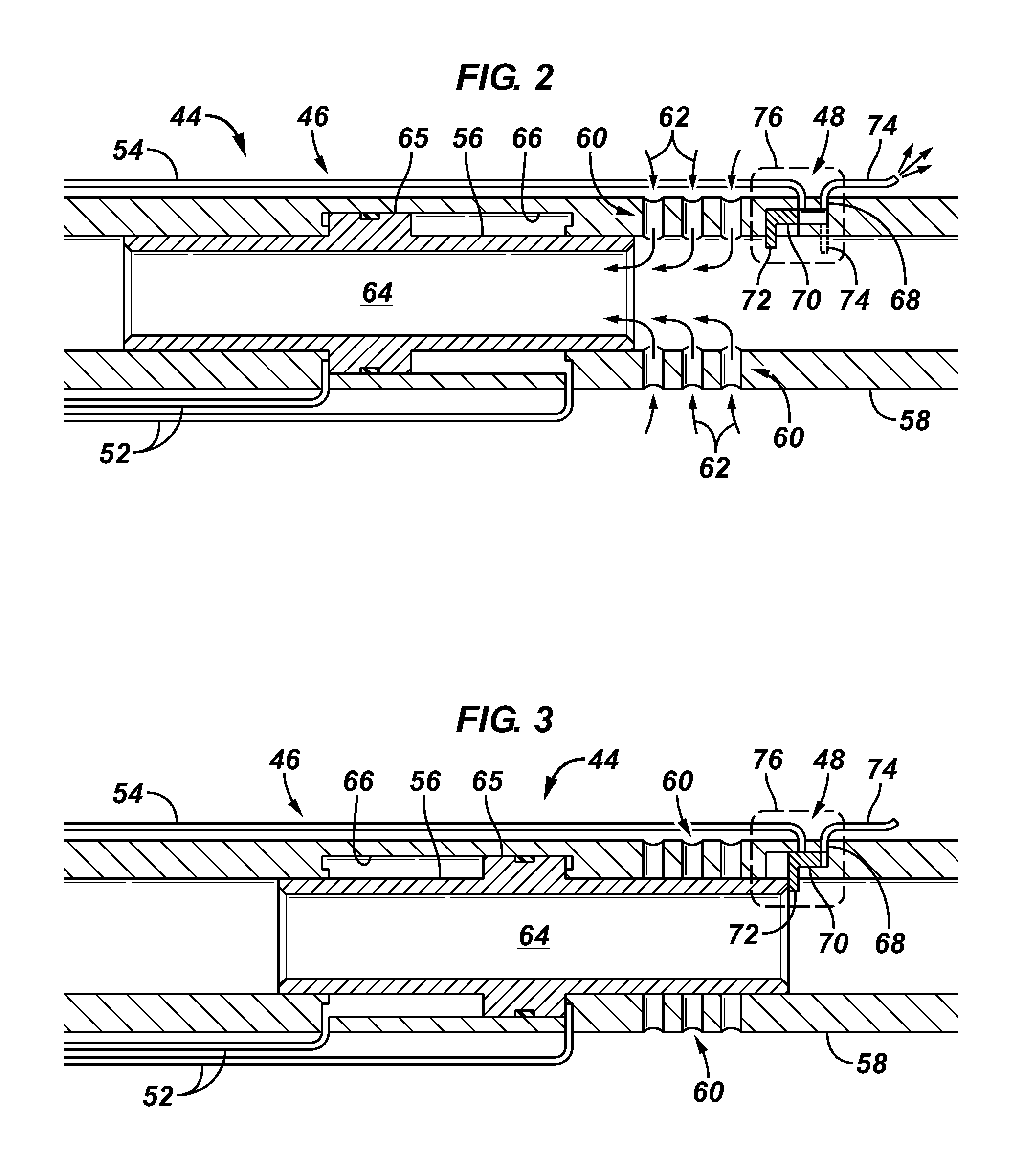
[0012]The disclosure herein generally involves a system and methodology related to controlling fluid flows. For example, the system and methodology may be used to control fluid flows in a well application or in another suitable application. A flow control valve is provided to control a flow of fluid, such as a wellbore fluid flow, and an injection valve is coupled with the flow control valve to control injection of secondary injection fluid. In some applications, a mechanical link couples the flow control valve and the injection valve, e.g. chemical injection valve, such that actuation of the flow control valve ...


PUM


Abstract

A technique facilitates controlling fluid flows, such as fluid flows in a downhole well zone or zones. A flow control valve is employed to control a fluid flow and is operationally linked with an injection valve. Actuation of the flow control valve is used to automatically actuate the injection valve between corresponding positions allowing or blocking fluid injection. Closing or opening of the flow control valve thus results in a desired corresponding action of the injection valve, such as blocking flow or allowing flow through the injection valve.

Description

CROSS-REFERENCE TO RELATED APPLICATION[0001]The present document is based on and claims priority to U.S. Provisional Application Ser. No.: 61 / 526,531, filed Aug. 23, 2011, incorporated herein by reference.BACKGROUND[0002]Chemical injection is used in oilfield applications to mitigate formation of scale, to counteract corrosion, and / or to treat the produced fluids in other ways to alter chemical properties in the downhole environment. In many applications, a single point chemical injection is performed above or below a production packer. The chemical injection is generally continuous and non-selective, i.e. the amount of injected fluid into a specific zone cannot easily be varied over time and in relation to other injection points in the well. Sometimes injected chemicals can build up in an isolated zone and are potentially damaging to the reservoir and associated completion equipment due to the increasing concentration of foreign chemical constituents. Over-injection also represents...

Claims


Application Information

Patent Timeline
Patent Type & Authority Applications(United States)
IPC IPC(8): E21B34/00E21B34/06G05D7/03
CPCE21B2034/007E21B34/10E21B2200/06E21B41/02E21B43/16
Inventor PATEL, DINESHLORETZ, IVES D.PROST, JEROME
Owner SCHLUMBERGER TECH CORP
Why Eureka
Try Eureka