
Radial shaft seal with dust exclusion and hydrodynamic sealing feature

Inactive Publication Date: 2013-02-28
FEDERAL MOGUL MOTORPARTS LLC
View PDF6 Cites 2 Cited by
  • Summary
  • Abstract
  • Description
  • Claims
  • Application Information

AI Technical Summary

Benefits of technology

The invention is a seal assembly that can be installed correctly even if there is a misalignment between the shaft and the hole. It also provides support for the seal lip when exposed to pressure on the oil side, preventing damage.

Problems solved by technology

It is known to incorporate spiral grooves in a seal lip to pump lubrication back to the oil-side of the seal, however, these grooves do not act to keep out dust or other contaminants.
This has undesirable affects on the seal, and ultimately reduces the useful life of the seal and possible bearings or other components that the seal is protecting.
Further, it is known to incorporate spiral grooves in a seal lip to keep dust and contamination on the air-side of the seal, however, these grooves do not act to maintain lubrication on the oil-side of the seal.
This has undesirable affects on the seal, and ultimately reduces the useful life of the seal and possible bearings or other components that the seal is protecting.

Method used


Image

  • Radial shaft seal with dust exclusion and hydrodynamic sealing feature
  • Radial shaft seal with dust exclusion and hydrodynamic sealing feature
  • Radial shaft seal with dust exclusion and hydrodynamic sealing feature

Examples


Embodiment Construction

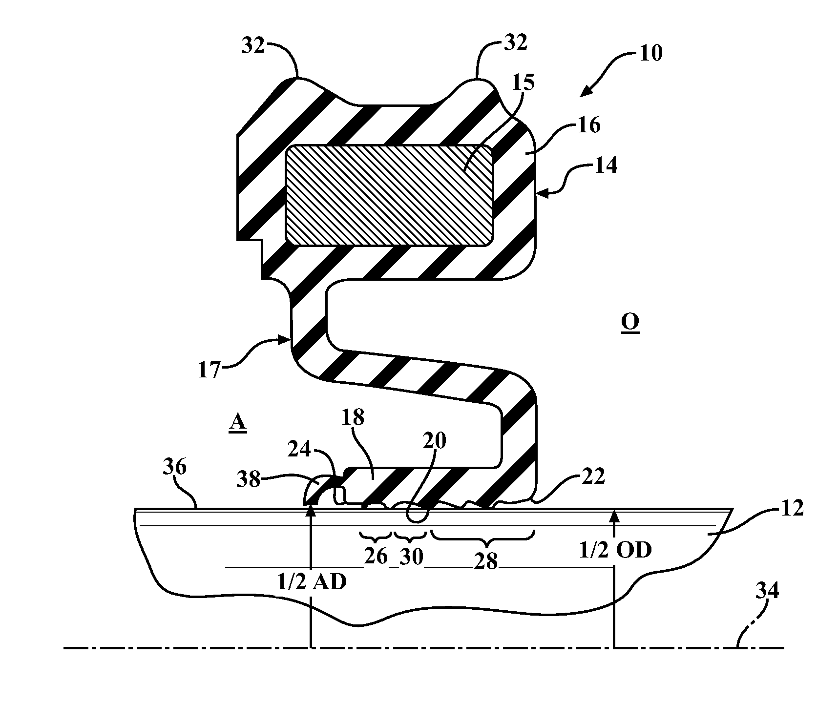
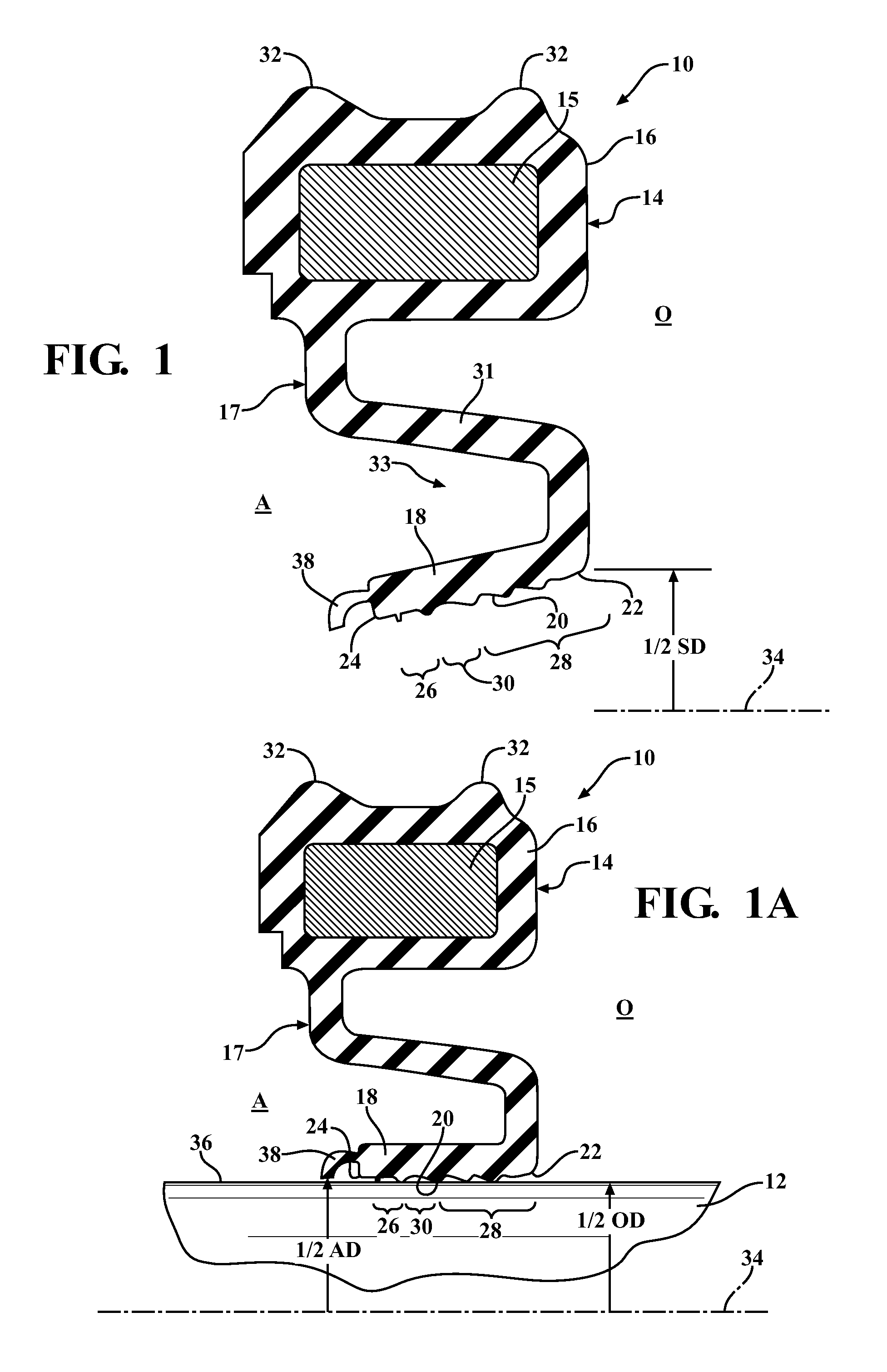
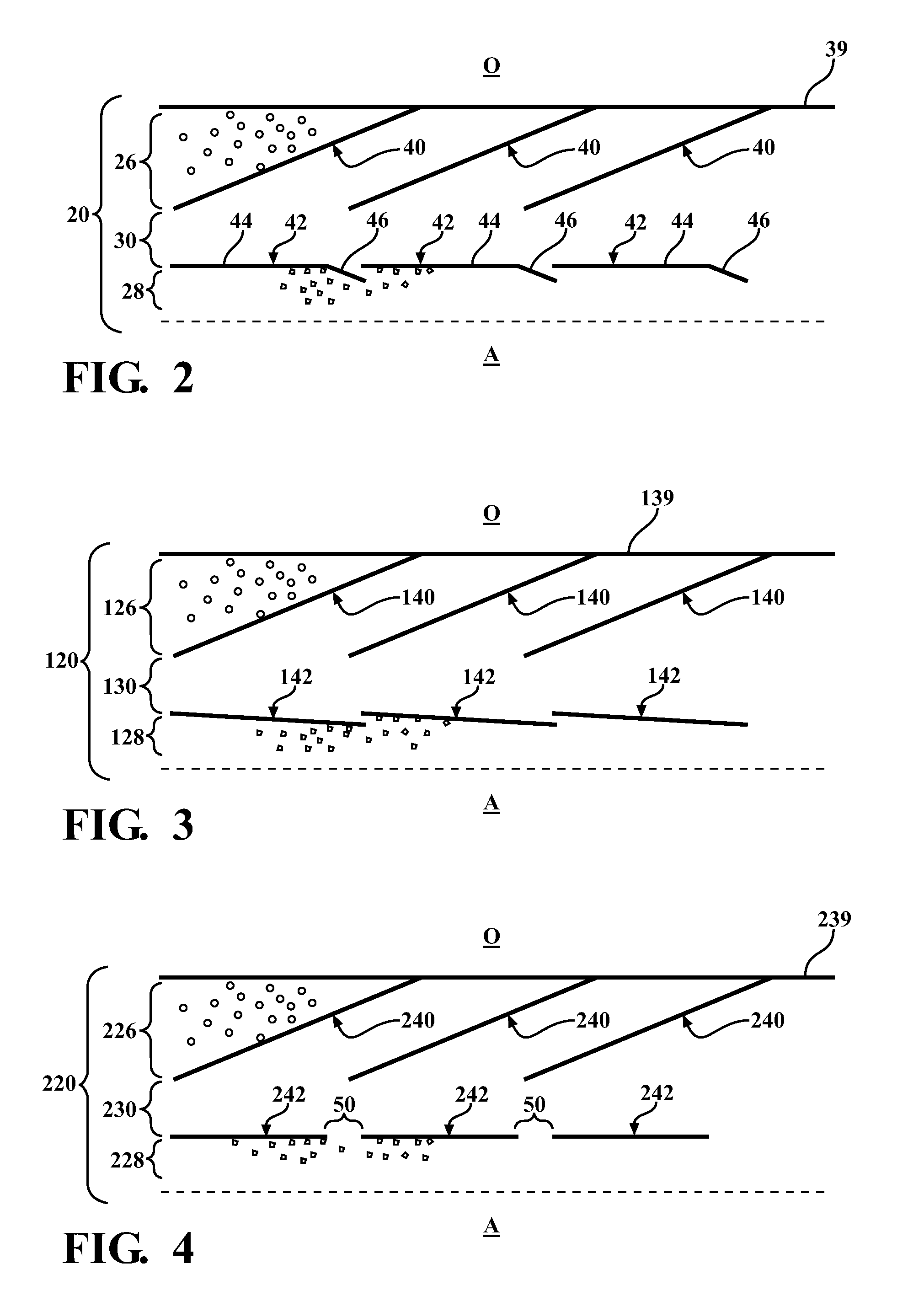
[0018]Referring in more detail to the drawings, FIGS. 1 and 1A illustrate a radial shaft seal, referred to hereafter as seal 10, constructed in accordance with one aspect of the invention, wherein the seal is suitable for use in a crankcase application, by way of example and without limitation, for sealing about a rotatable shaft 12 in a radial shaft seal assembly. The seal 10 has an oil-side O and an axially opposite air-side A, in relation to the orientation of the seal 10 when installed, with the oil-side O facing the interior of the application being sealed and the air-side A facing the outside environment of the application being sealed. The seal 10 includes a mounting portion, such as an outer case, also referred to as collar 14, provided as a metal or polymeric annulus or ring structure 15 with an elastomeric seal material 16 attached thereto. The elastomeric material 16 forms a seal body 17 and extends radially inwardly to provide a seal lip 18. The seal lip 18 has an annula...


PUM


Abstract

A radial shaft seal configured for receipt in a housing and about a shaft to sealingly isolate an air-side of the shaft seal from an oil-side of the shaft seal is provided. The seal includes an annular mounting portion and a seal lip operably attached to the mounting portion. The seal lip has an annular inner sealing surface extending axially between an oil-side end and a free air-side end. The inner sealing surface has a first groove region extending along the shaft in sealed engagement therewith and a second groove region extending along the shaft in sealed engagement therewith. The first groove region and the second groove region are spaced axially from one another by an intermediate non-grooved region. The first groove region is configured to direct contamination toward the air-side of the seal and the second groove region is configured to direct lubrication toward the oil-side of the seal.

Description

BACKGROUND OF THE INVENTION[0001]1. Technical Field[0002]This invention relates generally to dynamic oil seals of the type for creating a fluid tight seal between a rotating shaft and a housing.[0003]2. Related Art[0004]Dynamic radial shaft oil seals are designed to have a so-called “oil-side” of the seal and an “air-side.” These designations pertain to the orientation of the seal when installed, with the oil-side facing the interior of the housing and in communication with the oil, whereas the air-side faces outwardly and is exposed to the air.[0005]During use, it is desirable to keep dust and other contaminants on the air-side of the seal while maintaining lubrication on the oil-side of the seal. It is known to incorporate spiral grooves in a seal lip to pump lubrication back to the oil-side of the seal, however, these grooves do not act to keep out dust or other contaminants. As a matter of fact, if dust or contamination enters the grooves, it will tend to be pumped along with lu...

Claims


Application Information

Patent Timeline
IPC IPC(8): F16J15/32
CPCF16J15/3224F16J15/3244
Inventor PAYNE, ANDREWSEDLAR, BRENT R.TOTH, DAVID M.HATCH, FREDERICK R.
Owner FEDERAL MOGUL MOTORPARTS LLC
Learn More