
Imaging optical system, imaging device and imaging system

a technology of applied in the field of imaging optical system and imaging device, can solve the problems of increasing the size of the substrate, unable to reduce the number of lenses that make up the wide-angle lens,

Active Publication Date: 2013-02-28
RICOH KK
View PDF3 Cites 28 Cited by
  • Summary
  • Abstract
  • Description
  • Claims
  • Application Information

AI Technical Summary

Benefits of technology

The invention aims to solve a problem where a light beam is blocked by the substrate of an imaging optical system in an imaging device. It provides a solution for small imaging devices and imaging systems.

Problems solved by technology

Thus, it is difficult to reduce the number of lenses constituting the wide-angle lens.
Consequently, the size of the substrate is inevitably increased larger than the size of the imaging sensor.
Japanese Patent Application Publication No. 2010-271675 does not disclose a technique relative to vignetting of an incident light beam by such a substrate.

Method used


Image

  • Imaging optical system, imaging device and imaging system
  • Imaging optical system, imaging device and imaging system
  • Imaging optical system, imaging device and imaging system

Examples


example

[0125]

f = 0.75, No = 2.14, ω = 190 DEGREESSURFACENUMBERRDNdνd 117.11.21.83480742.725324 27.42.27 3*−18090.81.53113155.753858 4*4.582 517.10.71.63999960.078127 62.51.6 7∞0.3 8∞51.83400037.160487 9∞1.9210∞ (APERTURE STOP)0.151193.21.061.92286018.89691212−6.561.113∞−0.1143.371.861.75499852.32143415−30.71.92286018.8969121630.3 17*2.71.971.53113155.753858 18*−2.190.819∞0.41.51633064.14202220∞021∞0.31.51633064.14202222∞0.323IMAGING SURFACE

[Aspheric Surface]

[0126]Surfaces having * (both surfaces of second lens in front group and both surfaces of final lens in back group) in the above data are aspheric surfaces.

[0127]An aspheric surface shape is expressed by the following known equation by using an inverse of a paraxial curvature radius (paraxial curvature) C, a height from an optical axis H, a conical constant K, and an aspheric surface coefficient of each order with X as the aspheric surface amount in the optical axis direction, and is defined by providing the paraxial curvature radius, c...


PUM


Abstract

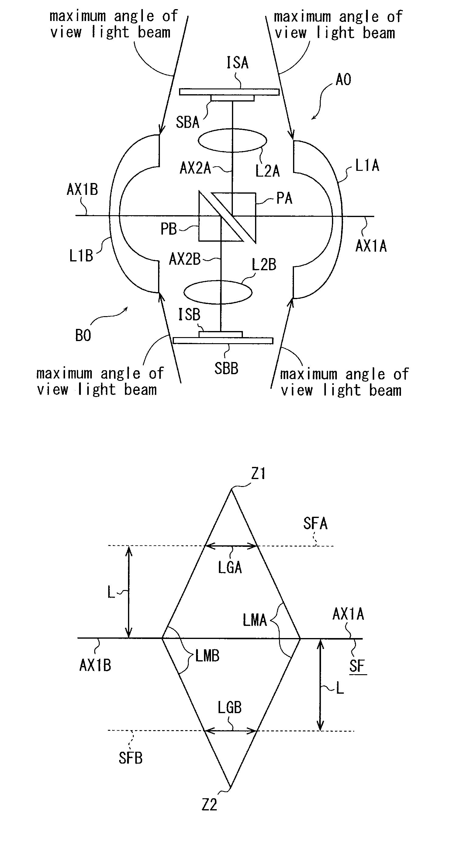
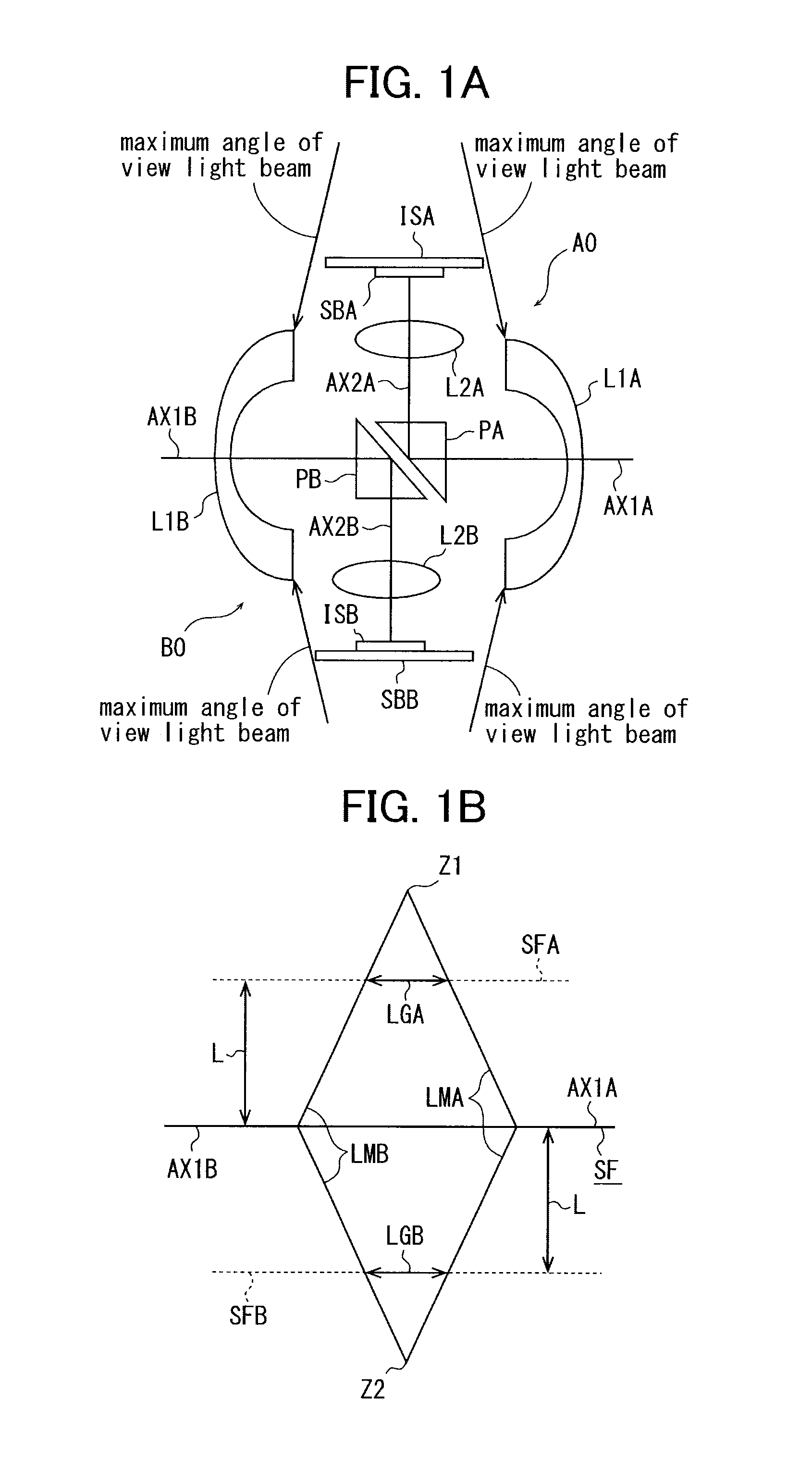
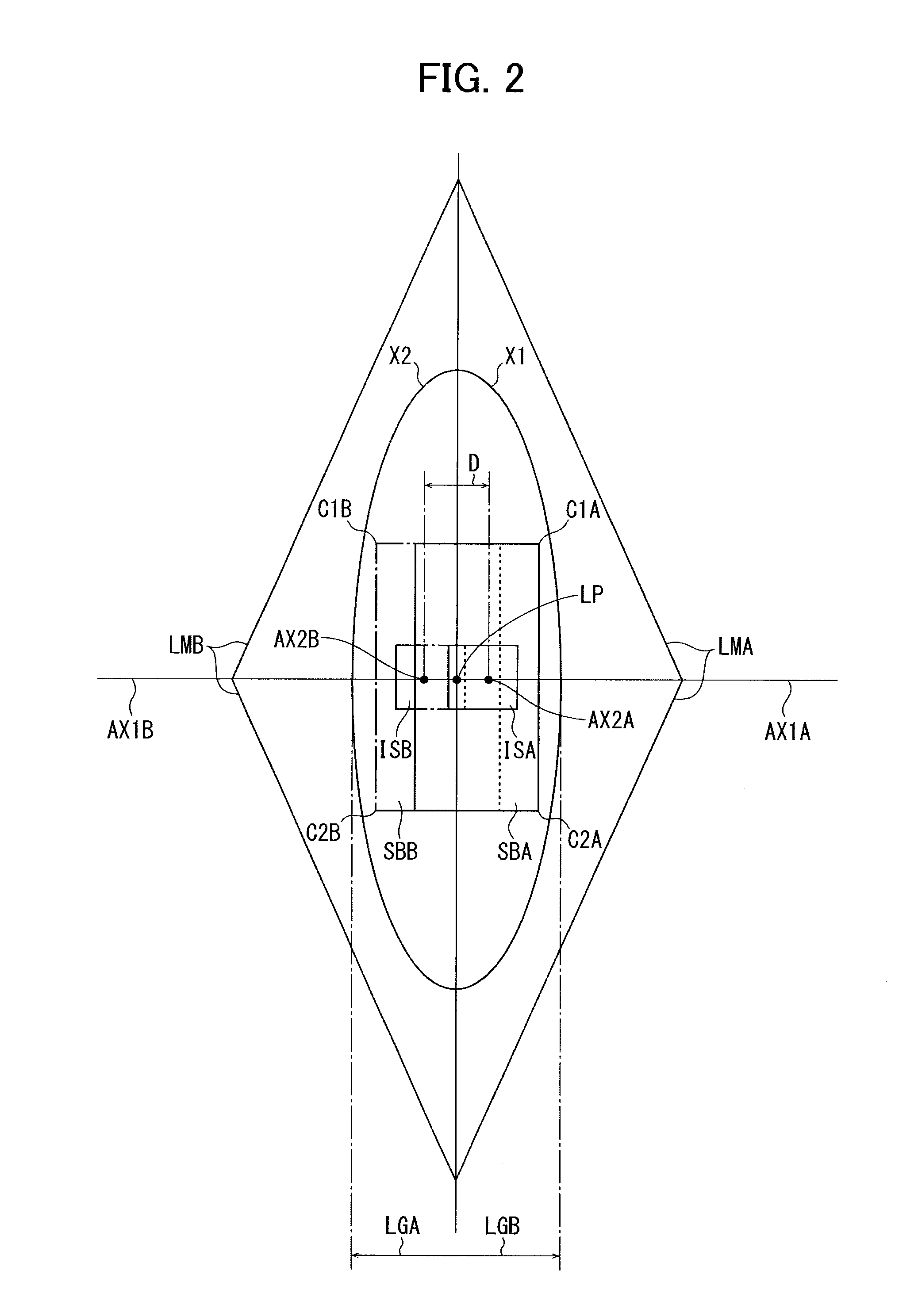
An imaging device includes two imaging optical systems each of the imaging optical systems including a wide-angle lens having an angle of view wider than 180 degrees, and an imaging sensor configured to image an image by the wide-angle lens, so as to obtain an image in a solid angle of 4π radian by synthesizing the images by the respective imaging optical systems, wherein the wide-angle lens of each of the imaging optical systems includes, in order from an object side to an image side, a front group having a negative power, a reflection surface and a back group having a positive power, and is configured to bend an optical axis of the front group by the reflection surface at 90 degrees toward the back group.

Description

PRIORITY CLAIM[0001]The present application is based on and claims priority from Japanese Patent Application No. 2011-188643, filed on Aug. 31, 2011 and Japanese Patent Application No. 2012-121269, filed on May 28, 2012, the disclosures of which are hereby incorporated by reference in their entirety.BACKGROUND[0002]1. Field of the Invention[0003]The present invention relates to an imaging optical system, imaging device and imaging system.[0004]2. Description of the Related Art[0005]An omnidirectional imaging device in which two imaging optical systems each including a wide-angle lens having an angle of view wider than 180 degrees and an imaging sensor for imaging an image by the wide-angle lens are combined, and an image by each of the imaging optical systems is synthesized to obtain an image in a solid angle of 4π radian is conventionally known (refer to Japanese Patent Application Publication No. 2010-271675).[0006]Such an omnidirectional imaging device is able to obtain omnidirec...

Claims


Application Information

Patent Timeline
IPC IPC(8): H04N7/00
CPCH04N5/2253H04N5/2254G02B17/023G02B13/06H04N5/23238H04N23/54H04N23/55H04N23/698
Inventor MASUDA, KENSUKETERAO, NORIYUKIIRINO, YOSHIAKITANAKA, TOMONORIIMAE, NOZOMIHARADA, TORUTAKENAKA, HIROKAZUYAMAMOTO, HIDEAKISAWAGUCHI, SATOSHIBESSHO, DAISUKESATOH, HIROYUKISHOHARA, MAKOTO
Owner RICOH KK
Learn More