

Vehicle lighting device
a technology for vehicle lighting and lighting fixtures, which is applied in the direction of point-like light sources, lighting and heating apparatus, transportation and packaging, etc., can solve the problems of unsatisfactory “lighting effect” of conventional light bulbs arranged in a ring or row-shaped array, and spectators are likely to think the vehicle light has some dark spots, so as to improve the warning capability
- Summary
- Abstract
- Description
- Claims
- Application Information
AI Technical Summary
Benefits of technology
Problems solved by technology
Method used
Image

Examples
first embodiment
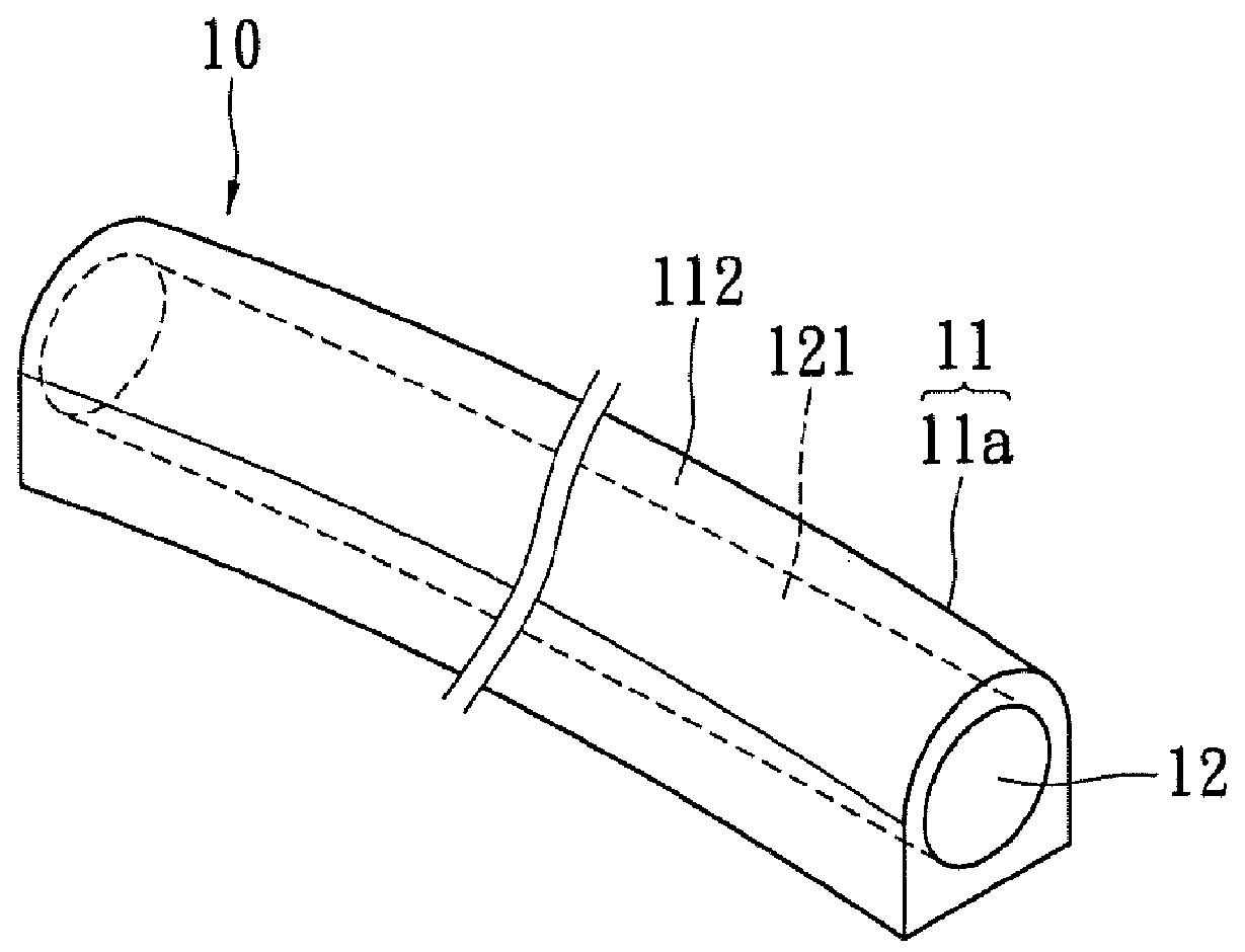
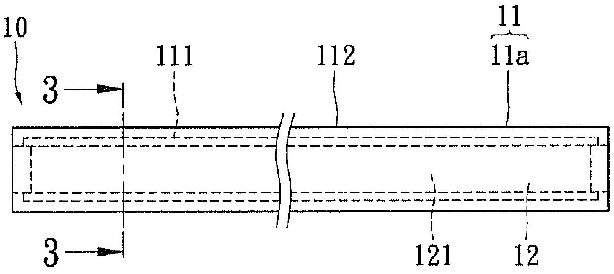
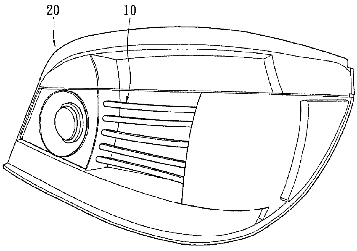
[0027]Please refer to FIGS. 1˜3, which show a vehicle lighting device 10 for the instant disclosure.
[0028]The vehicle lighting device 10 comprises an optical diffusing cover 11 and a light-emitting member 12. The technical features and characteristics of the preceding elements will be described in details. Please note, the directional references hereinafter are only for explaining purposes and not used for restricting the scope of the instant disclosure.
[0029]The optical diffusing cover 11 can be made of plastic or glass material. In the present embodiment, the optical diffusing cover 11 has a tubular strip body 11a. The strip body 11a can be straight or curved having two opposite ends. For the present embodiment, the strip body 11a takes a curved shape. When taking a front view (FIG. 2), the strip body 11a is seen straight. However, the curved shape of the strip body 11a can be seen with a top view thereof. The strip body 11a can be a one-piece structure formed integrally or an ass...
second embodiment
[0036]Please refer to FIG. 6, which shows the vehicle lighting device 10 of the instant disclosure. For this embodiment, the light-emitting member 12 includes two LEDs 122 arranged on the opposite ends of the strip body 11a with their light emitting surface facing toward each other. Specifically, one LED 122 is facing toward the left, while the other LED 122 is facing toward the right.
[0037]When the pair of LEDs 122 is turned on, both LEDs 122 would emit light opposite directions and toward each other. The light encounters the diffusion layer 113, which diffracts or scatters the light in a non-refractive manner in the strip body 11a. The diffracted or scattered light is then projected uniformly from the strip body 11a. Thereby, the vehicle lighting device 10 of this embodiment can also provide a light source having more uniform brightness for more effective warning capability.
[0038]Please refer to FIG. 7, which shows the vehicle lighting device 10 of a third embodiment of the instan...
fourth embodiment
[0041]Please refer to FIGS. 8˜11, which show the vehicle lighting device 10 for the instant disclosure.
[0042]The vehicle lighting device 10 of this embodiment comprises an optical diffusing cover 11, a light-emitting member 12, and a light-reflecting member 13. Differing from the previous embodiments, the optical diffusing cover 11 of this embodiment has a ring-shaped body 11b, such as shown in the figures. However, the shape of the optical diffusing cover 11 is not restricted, which may be circular, oval, polygonal, etc. The other difference is the addition of the light-reflecting member 13.
[0043]The ring-shaped body 11b can be a one-piece structure formed integrally or an assembled structure of two or more pieces. For the present embodiment, the ring-shape body 11b has a circular shape and is a two-piece assembled structure.
[0044]The ring-shaped body 11b has the inner surface 111, the outer surface 112, the diffusion layer 113, and two guide posts 114. Notably, the ring-shaped bod...
PUM
 Abstract
Description
Claims
Application Information