Power compensation apparatus and method for renewable energy system

Active Publication Date: 2013-02-28
DELTA ELECTRONICS SHANGHAI CO LTD
View PDF6 Cites 57 Cited by
  • Summary
  • Abstract
  • Description
  • Claims
  • Application Information

AI Technical Summary

Benefits of technology

[0035]In the power compensation apparatus and method of the present invention, a plurality of converter modules are respectively positioned between any two phases of a three-phase AC electrical grid in a delta connection. The DC voltage from the energy storage unit is converted into an AC voltage through the H-bridge circuit in the converter module, so as to provide the capacitive reactive power compensation or inductive reactive power compensation to the AC electrical grid, thereby keeping the voltage of the electrical grid continuously stab

Problems solved by technology

This will significantly increase the reactive power load in the electrical grid, resulting in power factor (PF) decrease of the network and voltage decrease and line-loss increase of the network, thereby affecting the stability of the electrical grid.
Moreover, the active powe

Method used


Image

  • Power compensation apparatus and method for renewable energy system
  • Power compensation apparatus and method for renewable energy system
  • Power compensation apparatus and method for renewable energy system

Examples


Embodiment Construction

[0043]In order to make the technical contents of the present invention more detailed and more comprehensive, various embodiments of the present invention are described below with reference to the accompanying drawings. Wherever possible, the same reference numbers are used in the drawings and the description to refer to the same or like parts. However, those of ordinary skills in the art should understand that the embodiments described below are not used for limiting the scope of the present invention. Moreover, the accompanying drawings are only used for illustration and are not drawn to scale. Specific implementations in various aspects of the present invention are further described in details below with reference to the accompanying drawings.

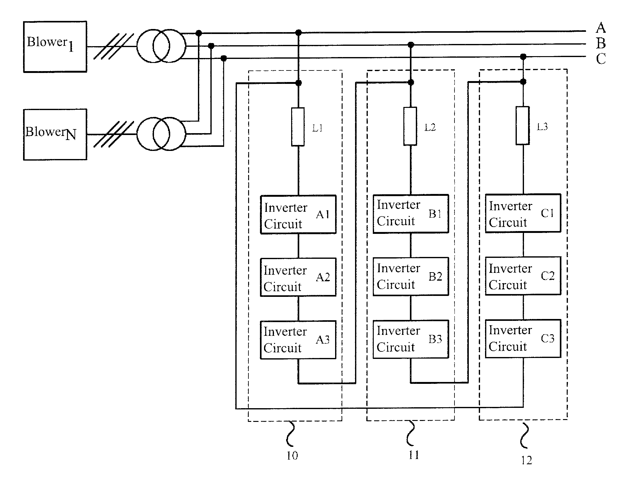
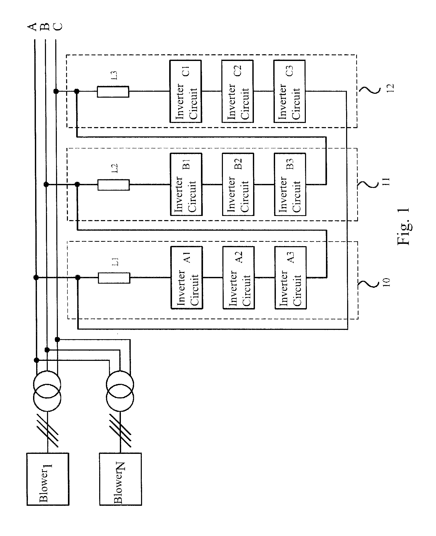
[0044]FIG. 1 illustrates an overall structure view of a power compensation apparatus for a renewable energy system according to an aspect of the present invention. Referring to FIG. 1, a blower 1 is electrically connected to an AC electrical ...


PUM


Abstract

A power compensation apparatus for a renewable energy system includes a plurality of converter modules positioned between any two phases of a three-phase AC electrical grid, each converter module including a plurality of inverter circuits connected in series. Each inverter circuit includes an energy storage unit for providing a direct current (DC) voltage; a capacitor connected to the energy storage unit; and an H-bridge circuit converting the DC voltage into an alternating current (AC) voltage. The converter modules perform reactive power compensation and active power regulation on the electrical grid in a delta connection. A plurality of converter modules are respectively positioned between any two phases of the electrical grid in a delta connection, so as to keep the voltage of the electrical grid continuously stable when the voltage of the electrical grid fluctuates, and also compensate load current when system load is not balanced.

Description

RELATED APPLICATIONS[0001]This application claims priority to Chinese Application Serial Number 201110240936.8, filed Aug. 22, 2011, which is herein incorporated by reference.BACKGROUND[0002]1. Field of Invention[0003]The present invention relates to power compensation techniques used for an alternating current (AC) electrical grid, and more particularly relates to a power compensation apparatus and a power compensation method which are suitable for use in a renewable energy system.[0004]2. Description of Related Art[0005]For an electrical grid, there are two types of electrical power for a power supply load, which includes active power and reactive power. The active power is the electrical power required for maintaining normal operation of a powered device; and, the reactive power is relative abstract, which is the electrical power used in electric and magnetic fields of an electrical circuit for creating and maintaining a magnetic field in an electrical apparatus. Generally, any e...

Claims


Application Information

Patent Timeline
IPC IPC(8): H02M7/5387
CPCH02M7/5387Y02E40/34H02M1/42H02M7/487H02J3/1807Y02B70/12H02J3/16Y02B70/10Y02E40/30
Inventor WANG, CHANG-YONGCHEN, QING
Owner DELTA ELECTRONICS SHANGHAI CO LTD
Why Eureka
Try Eureka