Adjusting Method and System of Intelligent Vehicle Imaging Device

Inactive Publication Date: 2013-02-28
AUTOEQUIPS TECH CO LTD
View PDF4 Cites 57 Cited by
  • Summary
  • Abstract
  • Description
  • Claims
  • Application Information

AI Technical Summary

Benefits of technology

[0008]According to one embodiment of the present invention, an adjusting method of intelligent vehicle imaging device is provided. In this invention, at least one real feature point used for comparison is disposed in a monitoring area around a vehicle. One or more images are captured by single or plural cameras around a vehicle. The image is transmitted to the controller and displayed on a touch display panel. The controller performs image processing including un-distortion calibration, homograph transformation, and image stitching. In order to perform homograph transformation, a p

Problems solved by technology

However, internal parameters of the conventional cameras used for the vehicle imaging system have been set before shipping, and a common driver cannot adjust the vehicle imaging system according to personal habits or road conditions.
In other words, different cameras installed for vehicle imaging system give different view results based on the lenses and sensors used, which i

Method used


Image

  • Adjusting Method and System of Intelligent Vehicle Imaging Device
  • Adjusting Method and System of Intelligent Vehicle Imaging Device
  • Adjusting Method and System of Intelligent Vehicle Imaging Device

Examples


Embodiment Construction

[0024]In the following detailed description, for purposes of explanation, numerous specific details are set forth in order to provide a thorough understanding of the disclosed embodiments. It will be apparent, however, that one or more embodiments may be practiced without these specific details. In other instances, well-known structures and devices are schematically depicted in order to simplify the drawings.

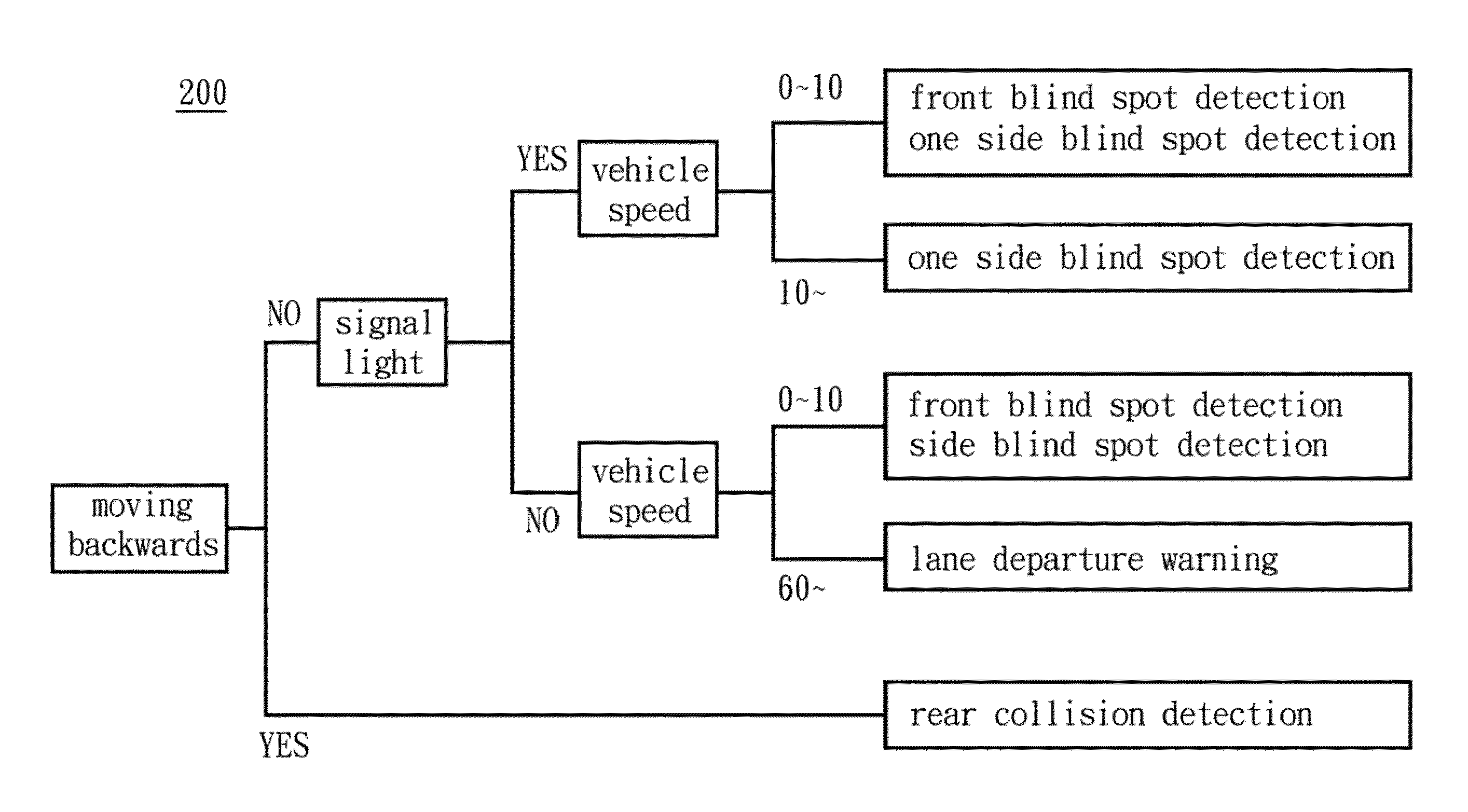
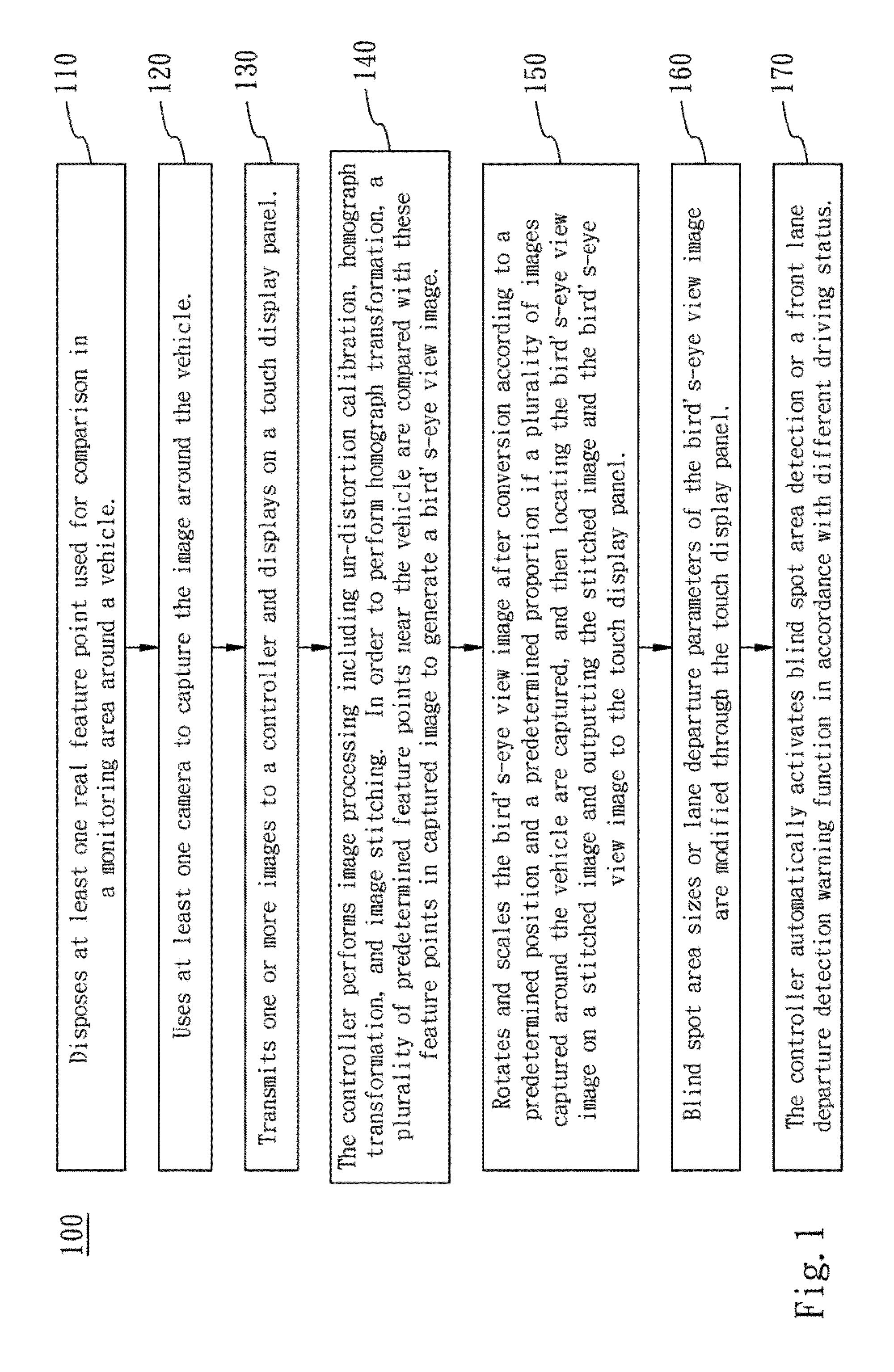
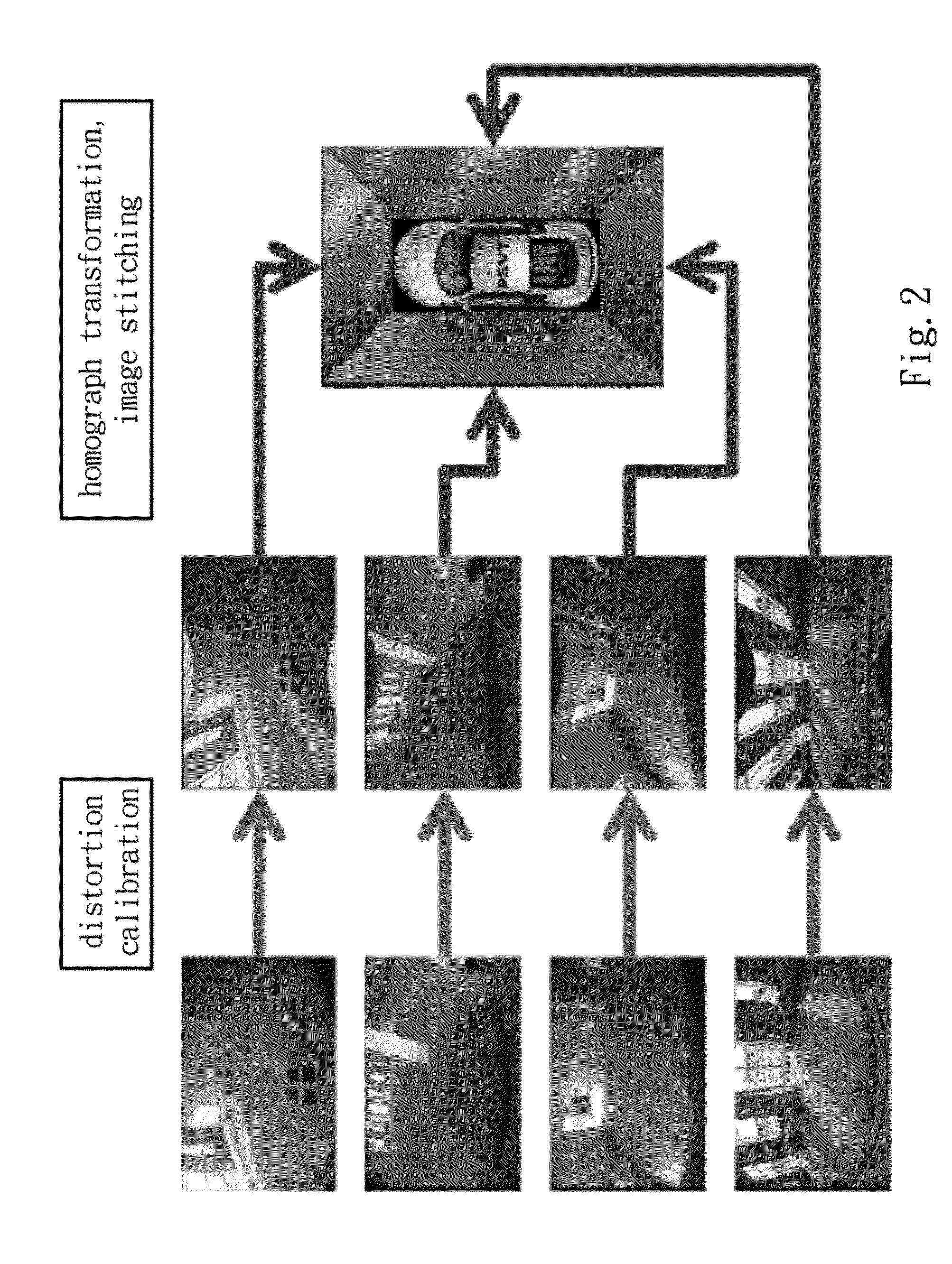
[0025]FIG. 1 is a flow chart showing an adjustment method of an intelligent vehicle imaging system according to an embodiment of the present invention. As shown in FIG. 1, an adjustment method of intelligent vehicle imaging system includes following steps. Step 110 is performed for disposing at least one real feature point used for comparison in a monitoring area around a vehicle. Step 120 is performed for using at least one camera to capture the image around the vehicle. Step 130 is performed for transmitting one or more images to a controller and displays on a touch display pa...


PUM


Abstract

An adjusting method and an adjusting system of an intelligent vehicle imaging device are provided, wherein a real feature point for comparison is disposed in a monitoring area around a vehicle. A camera captures images around the vehicle. The images are transmitted to the controller and displayed on a touch display panel. The controller performs image processing on the images and the real feature point, and compares the real feature point with position data of predetermined feature points, and generates a bird's-eye view image. If the images are captured, the bird's-eye view image is rotated and scaled after conversion according to a predetermined position and a predetermined proportion and then is located on a stitched image and outputted. A blind spot area size or a lane departure parameter is selected through the touch display panel, and the stitched image is adjusted through the touch display panel.

Description

RELATED APPLICATIONS[0001]The application claims priority to Taiwan Application Serial Number 100131365, filed Aug. 31, 2011, which is herein incorporated by reference.BACKGROUND[0002]1. Technical Field[0003]The present invention relates to an adjusting method and an adjusting system of an intelligent vehicle imaging device. More particularly, the present disclosure relates to an adjusting method and a system of an intelligent vehicle imaging device by using a touch display panel. The present invention sends warning messages regarding blind spot area detection and lane departure detection to a driver according to different driving statuses.[0004]2. Description of Related Art[0005]On the design concepts, modern vehicles not only are used as means of transportation but also pursues driving comfort, operability and safety, such as an electronic Anti-lock Brake System (ABS), airbags, a vehicle imaging system, etc., which are all used for providing an improved driving environment for dri...

Claims


Application Information

Patent Timeline
IPC IPC(8): G06F17/00
CPCB60R2300/402B60R2300/607B60R1/00B60R2300/802B60R2300/804B60R2300/70
Inventor LO, SHENG-CHIEHCHEN, CHIA-TSENGWANG, CHIH-YUAN
Owner AUTOEQUIPS TECH CO LTD
Why Eureka
Try Eureka