

Input apparatus
a technology of input apparatus and input input, which is applied in the field of input apparatus, can solve the problems that the type of input apparatus known in the art is difficult to be operated by the hand of the operator, and achieve the effect of facilitating the click input operation
- Summary
- Abstract
- Description
- Claims
- Application Information
AI Technical Summary
Benefits of technology
Problems solved by technology
Method used
Image

Examples
first embodiment
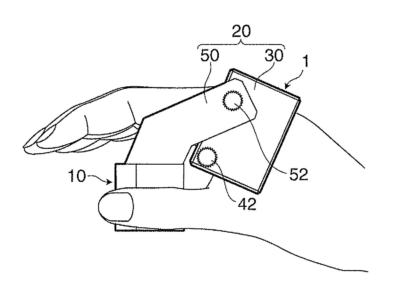
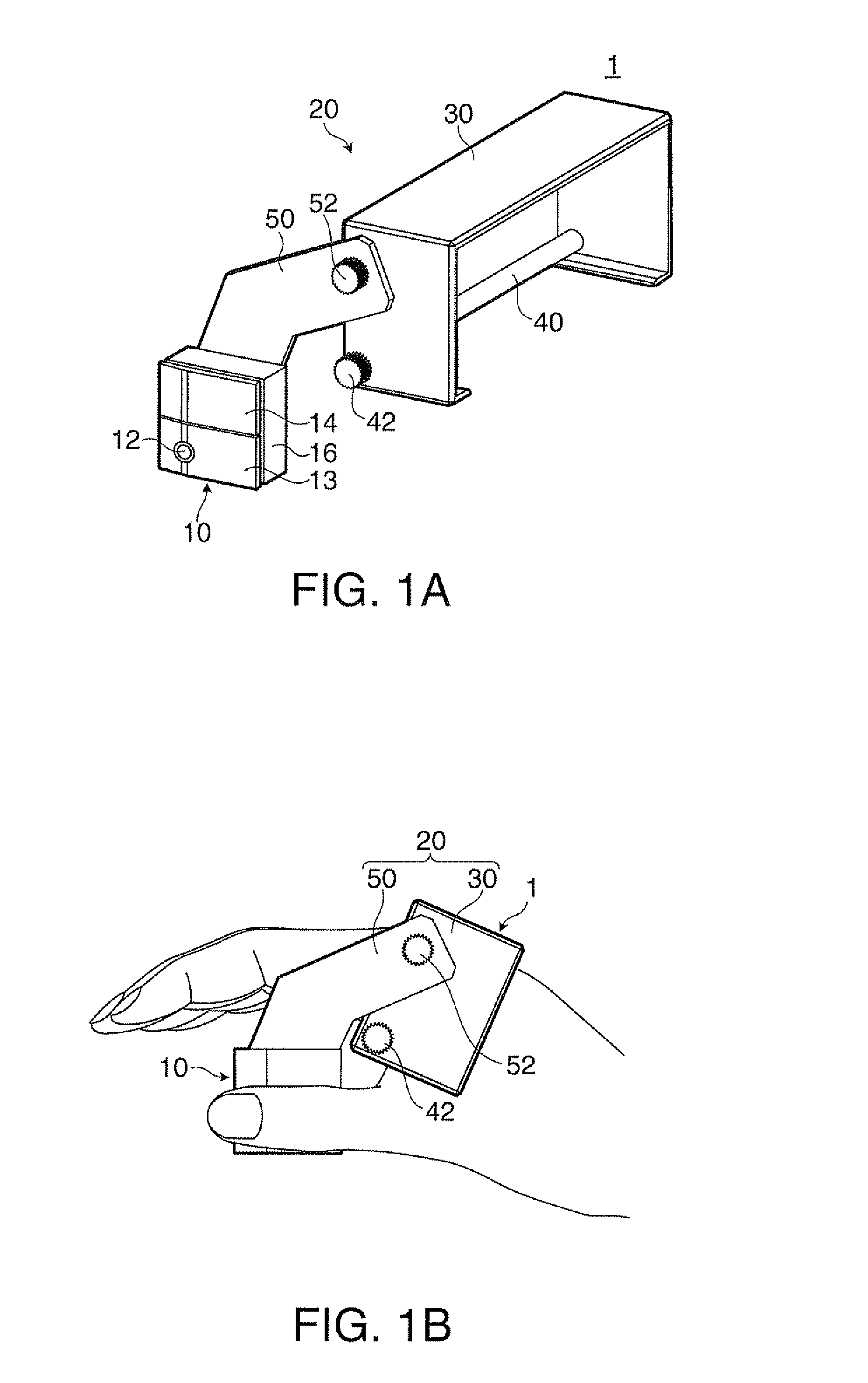
[0035]FIGS. 1A and 1B illustrate an input apparatus 1 according to a first embodiment. FIG. 1A is a perspective view of the input apparatus 1, while FIG. 1B is a side view of the input device I attached to a hand. FIG. 1B does not show a second fixing member 40 which is an invisible component as viewed in the figure.
[0036]As illustrated in FIGS. 1A and 1B, the input device 1 in the first embodiment includes a pointing device 10, and a fixing unit 20 for fixing the pointing device 10 to a hand of an operator. The input apparatus 1 is operated with the pointing device 10 attached to the hand via the fixing unit 20. FIGS. 1A and 1B and other figures show a condition of the input apparatus 1 attached to the right hand of the operator.
[0037]The input apparatus according to the embodiment of the invention may be an input apparatus attached to a left hand. The thumb of the left hand is positioned on the side opposite to the thumb of the right hand. Thus, the position of a carrying unit 50 ...
second embodiment
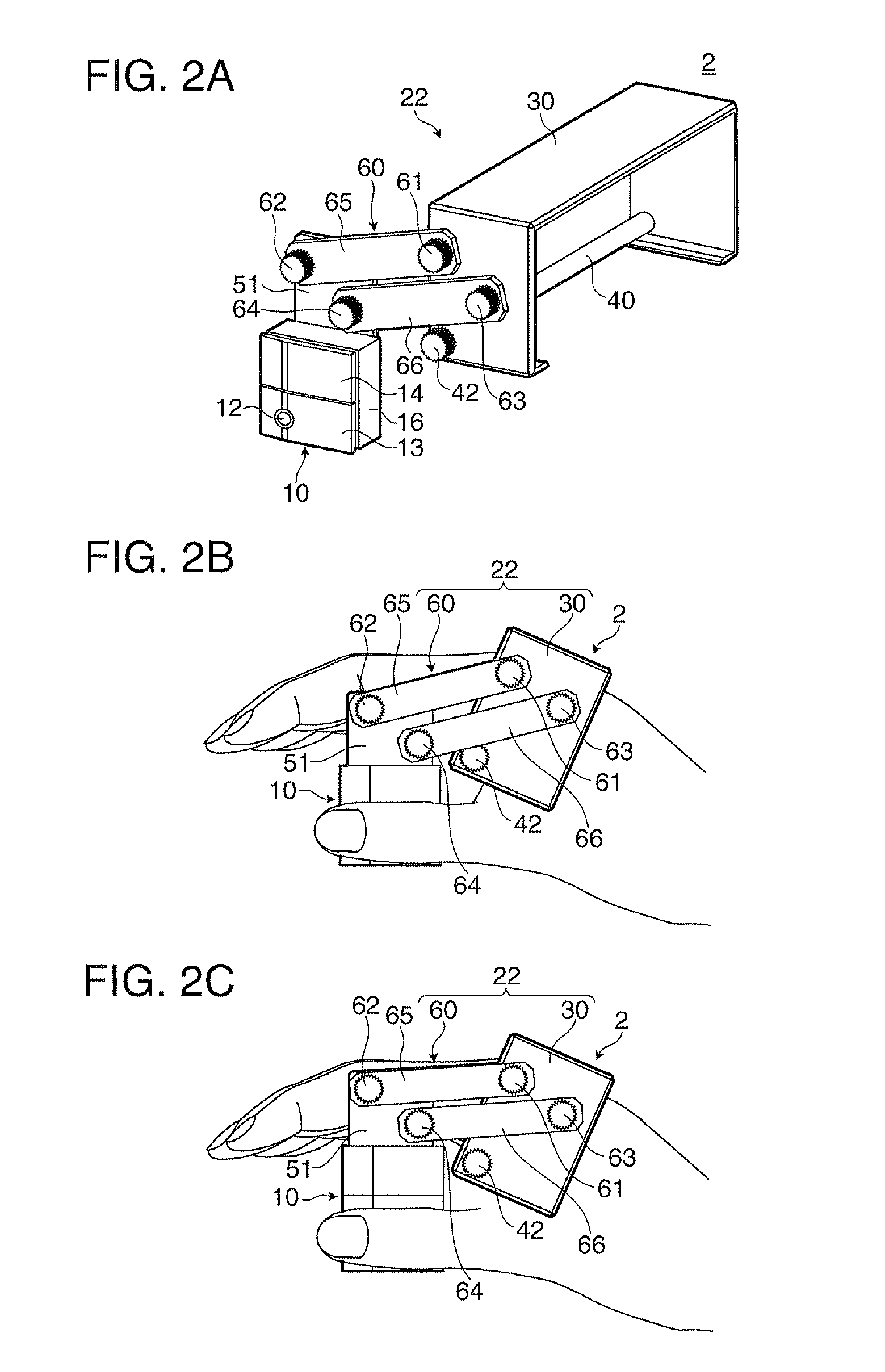
[0060]FIGS. 2A through 2C illustrate an input apparatus 2 according to a second embodiment. FIG. 2A is a perspective view of the input apparatus 2, FIG. 2B is a side view of the input apparatus 2 attached to a hand, and FIG. 2C is a side view illustrating a condition of a carrying unit 60 shifted from its position shown in FIG. 2B. FIG. 2B does not show the second fixing member 40 which is an invisible component in the figure.
[0061]The input apparatus 2 according to the second embodiment has a basic structure similar to that of the input apparatus 1 in the first embodiment. However, the input apparatus 2 is different from the input apparatus 1 in the first embodiment in that a link mechanism is provided on the input apparatus 2. More specifically, the input apparatus 2 according to the second embodiment has a link mechanism containing fixing screws 61, 62, 63, and 64, and link plates 65 and 66 as illustrated in FIGS. 2A through 2C. In other words, a fixing unit 22 has a shift mechan...
third embodiment
[0065]FIG. 3 is a perspective view illustrating an input apparatus 3 according to a third embodiment.
[0066]The input apparatus 3 in the third embodiment has a basic structure similar to that of the input apparatus 1 in the first embodiment. However, the input apparatus 3 is different from the input apparatus 1 in the first embodiment in the structure of the pointing device. More specifically, a pointing device 70 of the input apparatus 3 in the third embodiment has an input unit 72, a click button 74, a main unit 76, and a connection cord 78 as illustrated in FIG. 3. A fixing unit 24 included in this structure fixes the main unit 76 to the back side of the hand when the input apparatus 3 is attached to the hand.
[0067]The input unit 72 and the click button 74 in this embodiment have structures similar to the corresponding structures of the input unit 12 and the click button 14 in the first embodiment, respectively, and the same explanation of these components is not repeated herein.
[...
PUM
 Abstract
Description
Claims
Application Information