
Rotary device

A technology of rotary device and rotary body, which is applied in control device, transportation and packaging, earth mover/shovel, etc., can solve the problems of disharmonious vibration of rotary body, reduction of reduction ratio, and deterioration of angle measurement accuracy, etc. Achieve the effect of maintaining sports performance and suppressing vibration

Active Publication Date: 2021-01-29
SUMITOMO HEAVY IND LTD
View PDF8 Cites 0 Cited by
  • Summary
  • Abstract
  • Description
  • Claims
  • Application Information

AI Technical Summary

Problems solved by technology

[0004] This indirect method of measuring the angle of the rotating body has the advantage of not requiring a sensor for directly measuring the angle of the rotating body. On the other hand, the angle transmission error or backlash of the reducer becomes an error factor, and it has the accuracy of measuring the angle of the rotating body. exacerbated disadvantages
Furthermore, when the backlash reverses the rotation direction of the motor, a section (dead zone) in which the rotation of the swing motor is not transmitted to the swing body occurs. The gears on the side of the rotating body in the stopped state collide, causing the rotating body to vibrate inharmoniously
[0005] In an excavator using a hydraulic motor as a swing motor, the reduction in the reduction ratio due to the low responsiveness, low rotation and high torque of the hydraulic motor cannot be ignored in practical use.

Method used


Image

  • Rotary device
  • Rotary device
  • Rotary device

Examples


Embodiment Construction

[0050] Hereinafter, the present invention will be described based on preferred embodiments with reference to the drawings. The same or equivalent constituents, components, and processes shown in the drawings are given the same symbols, and redundant descriptions are appropriately omitted. Furthermore, the embodiments are illustrative rather than limiting the invention, and all the features or combinations thereof described in the embodiments do not necessarily constitute the essence of the invention.

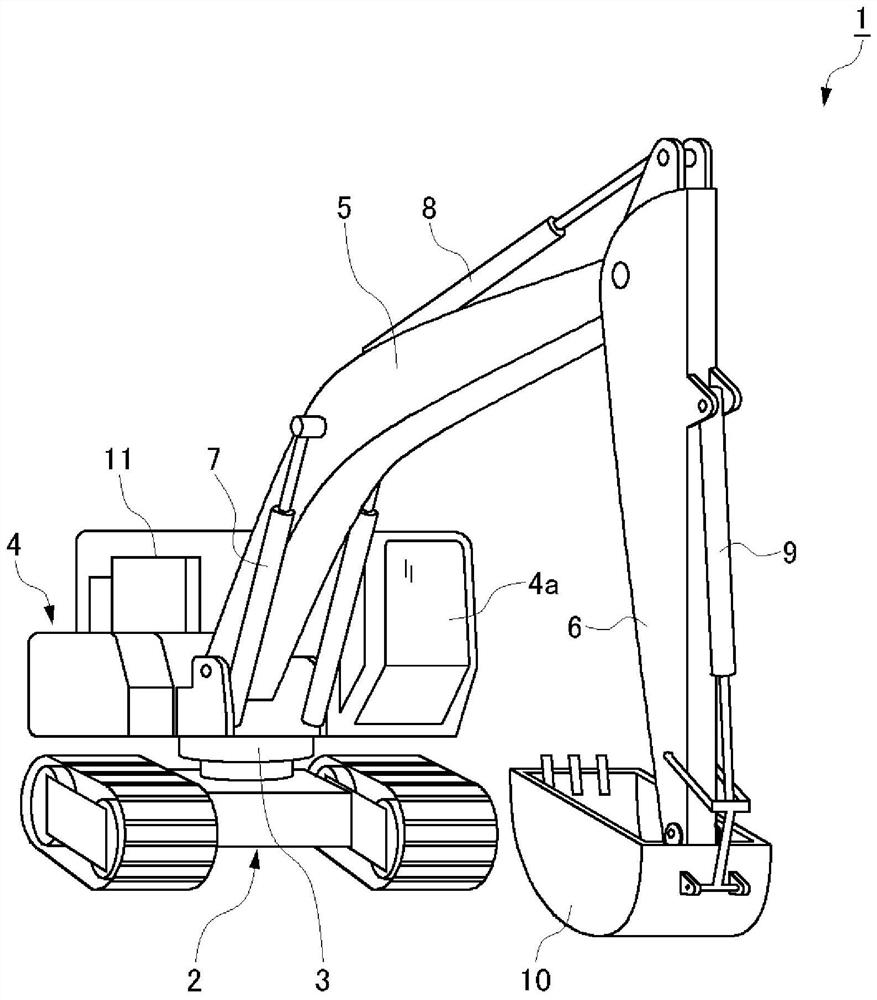
[0051] figure 1 It is a perspective view showing the appearance of a shovel 1 which is an example of the construction machine according to the embodiment. The shovel 1 mainly includes a traveling mechanism 2 and an upper revolving body (hereinafter, simply referred to as a revolving body) 4 rotatably mounted on an upper portion of the traveling mechanism 2 via a revolving mechanism 3 .

[0052] A boom 5 , an arm 6 hinged to the front end of the boom 5 , and a bucket 10 hinged ...


PUM


Abstract

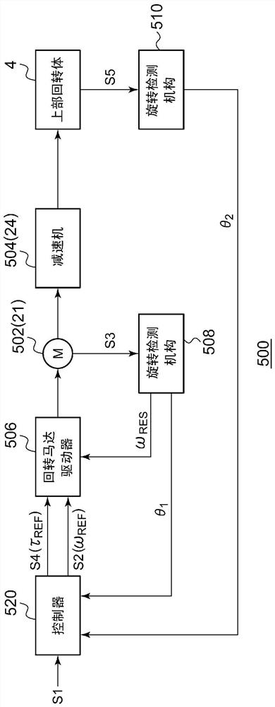
The invention provides a turning device. The speed reducer (504) transmits the rotation of the turning motor (502) to the turning body (4). A swing motor driver (506) drives the swing motor (502). (i) The non-idling section (T A ), the controller (520) controls the swing motor driver (506) according to the operation command value (S1). And, (ii) in the idling section (T B ), the controller (520) will reach the non-idling interval (T A ) until the rotary motor (502) rotates at high speed, and reaches the non-idling section (T B ) to control the swing motor driver (506) in such a way that the rotational speed or torque decreases.

Description

technical field [0001] The invention relates to a swivel device. Background technique [0002] In recent years, construction machines represented by power shovels and cranes are equipped with a turning device for turning an upper turning body. Generally, a swing device includes a swing motor for driving the swing body and a power transmission mechanism for transmitting the output of the swing motor to the swing body. A hydraulic motor or an electric motor (electric motor) can be used as the swing motor, and a speed reducer can be used as the power transmission mechanism. . [0003] Ideally, the rotation angle or the rotation speed of the slewing body is uniquely determined by the rotation angle and the rotation speed of the slewing motor, and the reduction ratio of the speed reducer. Therefore, as a method of measuring the angle of the revolving body in the excavator, a rotation angle sensor that directly obtains the rotation information (rotation angle, rotation speed, ro...

Claims


Application Information

Patent Timeline
Patent Type & Authority Patents(China)
IPC IPC(8): H02P23/04B60K17/04E02F9/22
CPCB60K17/04E02F9/22H02P29/00
Inventor 长井弘明
Owner SUMITOMO HEAVY IND LTD
Learn More