
Wire forming machine

A technology of forming machine and wire rod, applied in the direction of wire rod processing, wire manufacturing of springs, and other household appliances, etc., can solve the problem of high cost

Active Publication Date: 2020-11-24
ASAHI SEIKI INDUSTRIES
View PDF7 Cites 0 Cited by
  • Summary
  • Abstract
  • Description
  • Claims
  • Application Information

AI Technical Summary

Problems solved by technology

However, when the number of movable shafts increases, the overall size of the wire forming machine becomes larger and the cost becomes higher

Method used


Image

  • Wire forming machine
  • Wire forming machine
  • Wire forming machine

Examples


Embodiment Construction

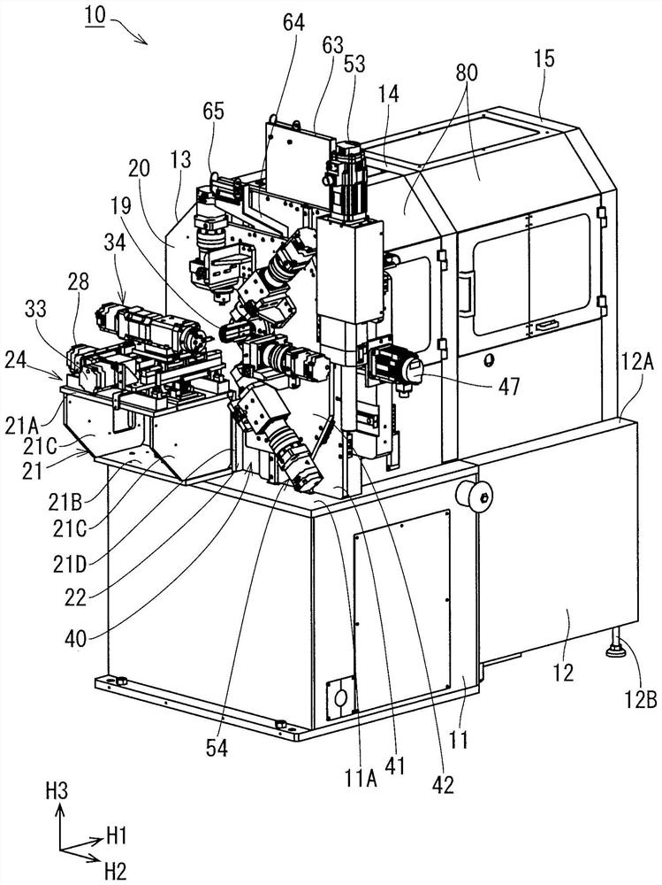
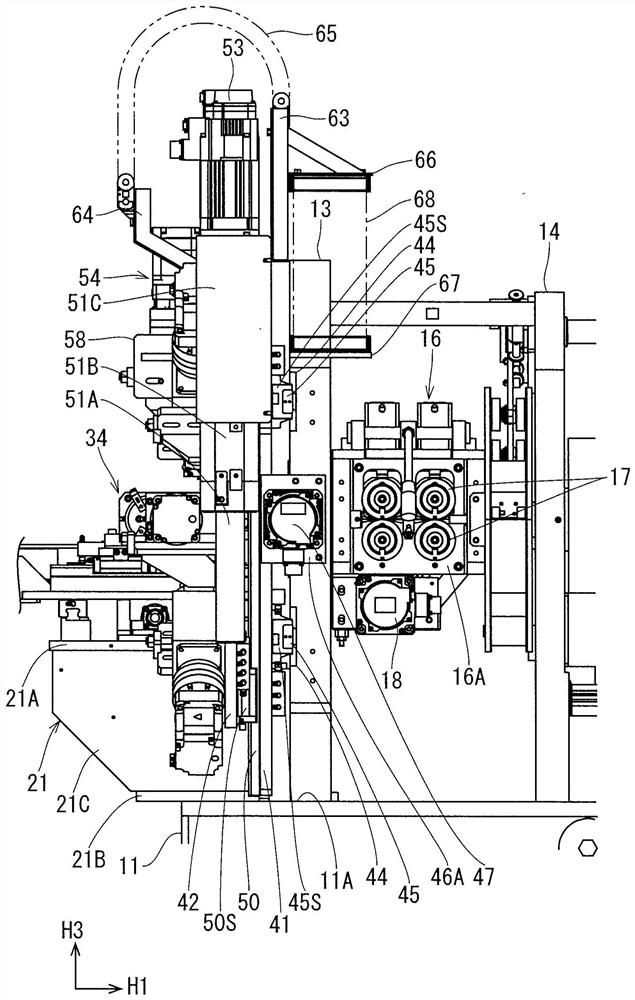
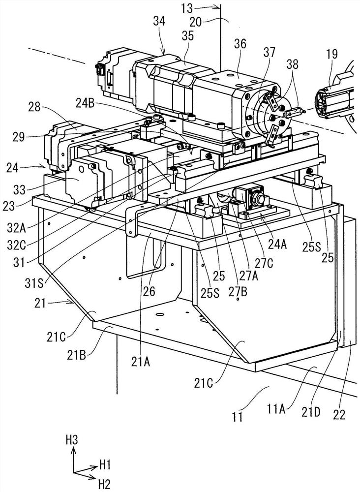
[0047] Below, refer to Figure 1 to Figure 10 , an embodiment of the wire forming machine 10 of the present disclosure will be described. Such as figure 1 As shown, the wire forming machine 10 is equipped with the 1st support stand 11 and the 2nd support stand 12 in parallel. Hereinafter, the direction in which the first support base 11 and the second support base 12 are arranged is referred to as the "front-rear direction H1", the side on which the first support base 11 is disposed is referred to as the "front side", and the opposite side is referred to as the "front side". "Rear side". In addition, the horizontal direction perpendicular to the front-back direction H1 is referred to as the horizontal direction H2, and the right side of the horizontal direction H2 when viewing the wire forming machine 10 from the front is simply referred to as the "right side", and the opposite side is simply referred to as the "left side". . Moreover, the vertical direction is called "up-...


PUM


Abstract

The purpose of the present disclosure is to provide a technique whereby the number of movable shafts of a tool of a wire forming machine can be easily changed and the overall wire forming machine canbe made compact. The wire forming machine (10) according to an embodiment is provided with a first XY table (40) on a substrate (13), and an extension support section (21) having a second base surface(23) orthogonal to a first base surface (20). A second XY table (24) is provided on a second base surface extending out of the support section, and the substrate (13) has a vertical first base surface (20) on the front side. The first XY table (40) has a sliding plate (42) having a recess (42A) capable of receiving the sleeve shaft (19), and the sliding plate is provided with a plurality of device fixing parts (70) capable of fixing the plurality of first tool moving devices (54) in a radial arrangement centered on the recess. The second XY table is provided with a second tool moving device (34).

Description

technical field [0001] The present disclosure relates to a wire forming machine that utilizes multiple tools to shape wire fed through a quill. Background technique [0002] Conventionally, as such a wire forming machine, there is known a wire forming machine having a mechanism in which a sleeve shaft protrudes from a central portion of a front surface of an upright substrate, and a protruding support portion protrudes from the front surface of the substrate. One side portion of the tool is protruded, and the tool is moved on the protruding support portion (for example, refer to Patent Document 1). [0003] prior art literature [0004] patent documents [0005] Patent Document 1: Japanese Patent Laid-Open No. 2019-5801 ( figure 1 ) [0006] In addition, in the wire forming machine, there are many movable shafts in the mechanism of the moving tool, the versatility is increased, and the shape of the wire formed product that can be formed has many variations. However, whe...

Claims


Application Information

Patent Timeline
Patent Type & Authority Applications(China)
IPC IPC(8): B21F35/00B21F23/00B21F1/02
CPCB21F35/00B21F23/00B21F1/02B21F1/008B21F1/006B21C1/02B21F3/04
Inventor 野岛高志多田慎吾
Owner ASAHI SEIKI INDUSTRIES
Learn More