Connector-connecting terminal treatment structure for shielded wires and method of producing connector-connecting terminal treatment structure for shielded wires

a terminal treatment and shielded wire technology, applied in the direction of dustproof/splashproof/drip-proof/waterproof/flameproof connection, securing/insulating coupling contact member, etc., can solve the problem of reducing the amount of sealing material to be kept at the portion intended to be waterproof, adversely affecting the waterproof ability, and increasing the probability of leaking of sealing material. , to achieve the effect of reducing the amount of sealing material to be kept at the portion

Inactive Publication Date: 2013-03-07
SUMITOMO WIRING SYST LTD
View PDF20 Cites 11 Cited by
  • Summary
  • Abstract
  • Description
  • Claims
  • Application Information

AI Technical Summary

Benefits of technology

[0007]In Related Art 1, however, the outer cover wraps around only the surface of the sealing material. Accordingly, there is a case where the sealing material leaks to the lateral sides of the outer cover when the sealing material is pressured so as to be more tightly attached to the wire core exposed portion. In addition, there is a demand for a waterproof function that can be imparted to a plurality of shielded wires as a whole. In such a case, gaps are formed among the wire core exposed portions and among sheaths of the plurality of shielded wires. Leaking of the sealing material thus becomes more likely. When the sealing material leaks to the lateral sides of the outer cover, the amount of the sealing material to be kept at the portion intended to be waterproofed is reduced, which may adversely affect a waterproof capability.

Problems solved by technology

Leaking of the sealing material thus becomes more likely.
When the sealing material leaks to the lateral sides of the outer cover, the amount of the sealing material to be kept at the portion intended to be waterproofed is reduced, which may adversely affect a waterproof capability.

Method used


Image

  • Connector-connecting terminal treatment structure for shielded wires and method of producing connector-connecting terminal treatment structure for shielded wires
  • Connector-connecting terminal treatment structure for shielded wires and method of producing connector-connecting terminal treatment structure for shielded wires
  • Connector-connecting terminal treatment structure for shielded wires and method of producing connector-connecting terminal treatment structure for shielded wires

Examples


Embodiment Construction

[0035]The particulars shown herein are by way of example and for purposes of illustrative discussion of the embodiments of the present invention only and are presented in the cause of providing what is believed to be the most useful and readily understood description of the principles and conceptual aspects of the present invention. In this regard, no attempt is made to show structural details of the present invention in more detail than is necessary for the fundamental understanding of the present invention, the description is taken with the drawings making apparent to those skilled in the art how the forms of the present invention may be embodied in practice.

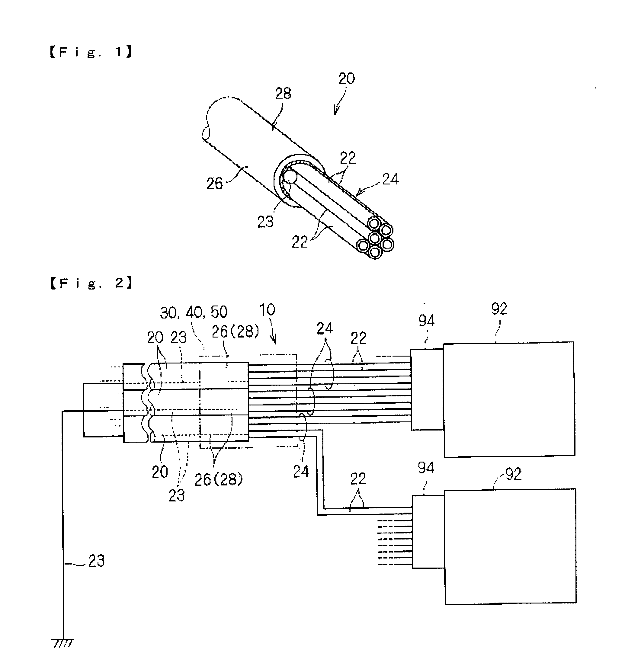
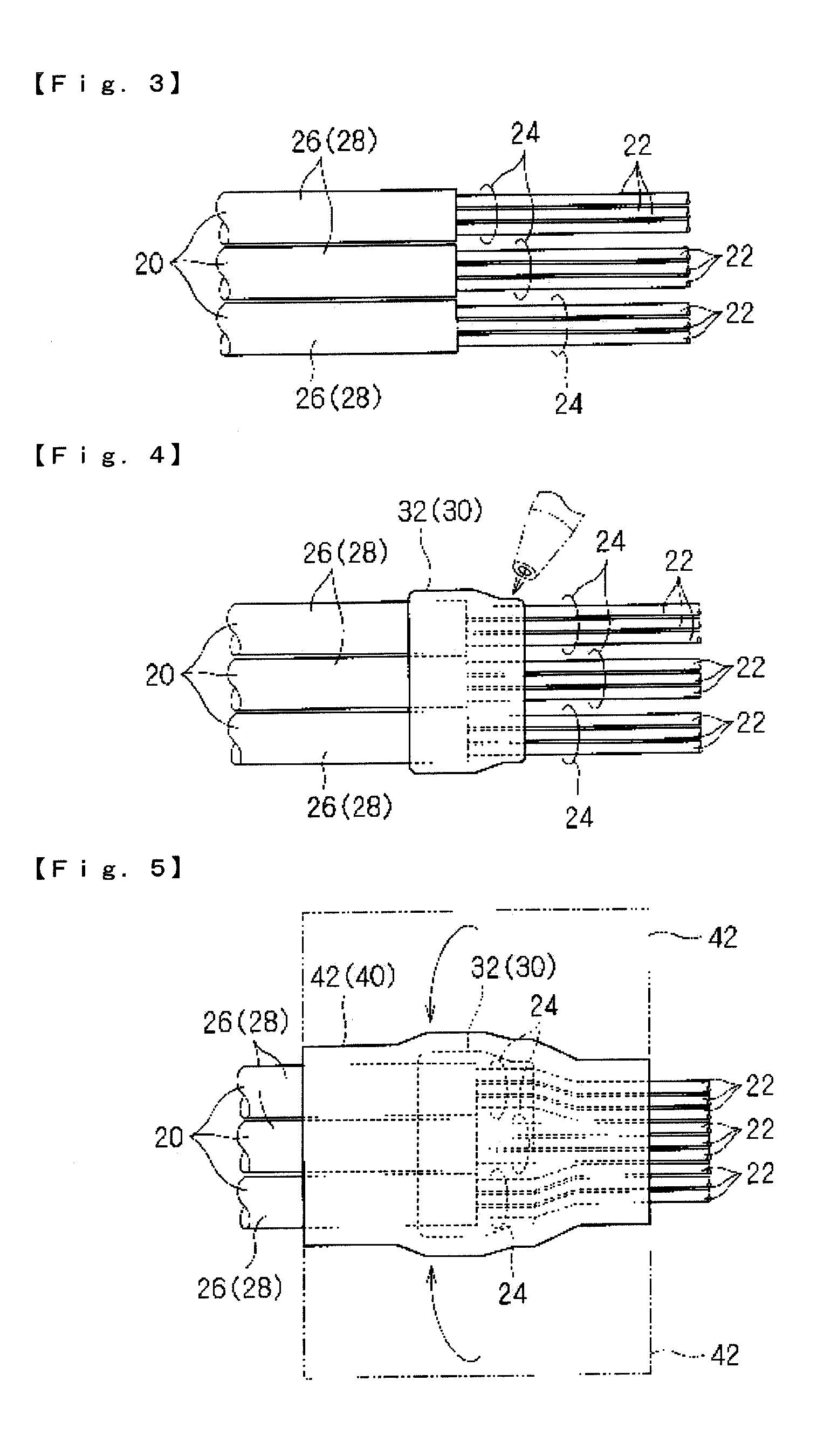
[0036]Hereinafter, a connector-connecting terminal treatment structure 10 for shielded wires according to the present invention and a method of producing the same are described (see FIGS. 2 and 6).

[0037][1. Shielded Wire]

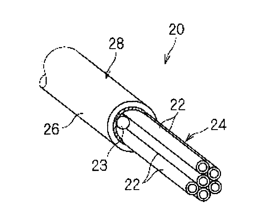
[0038]First, for convenience of descriptions, a shielded wire 20, a target here, is described (see FIG. 1)....


PUM


Abstract

A connector-connecting terminal treatment structure for shielded wires includes the plurality of shielded wires, a first water stopper, and a second water stopper. The plurality of shielded wires are arranged in parallel to one another, and each of the shielded wires has an exposed strand portion and a covered portion. The first water stopper is configured with a paste waterproof agent integrally covering a boundary portion between the exposed strand portions and the covered portions in the plurality of shielded wires. The sheet-like water stopper through which the paste waterproof agent does not penetrate is provided so as to cover the outer periphery of the first water stopper as well as to tightly attach to the outer periphery of the exposed strand portions and the covered portions at both the lateral sides of the first water stopper in the extending direction of the shielded wires.

Description

CROSS-REFERENCE TO RELATED APPLICATION[0001]The present application claims priority under 35 U.S.C. §119 of Japanese Application No. 2011-194891, filed on Sep. 7, 2011, which is herein expressly incorporated by reference in its entirety.BACKGROUND OF THE INVENTION[0002]1. Field of the Invention[0003]The present invention relates to a connector-connecting terminal treatment technology for shielded wires.[0004]2. Description of Related Art[0005]Related Art 1 discloses a technology that provides a waterproof function at a wire core exposed portion in which a wire core of a shielded wire is exposed. In shielding structure of the shielded wire in Related Art 1, the wire core exposed portion is covered by a paste sealing material that is configured with a conductive self-fusion adhesive material, such as butyl rubber and the like. The surface of the sealing material is wrapped by a sheet or tape outer cover.[0006]Related Art 1: Japanese Patent Laid-open Publication No. 2007-109684SUMMARY ...

Claims


Application Information

Patent Timeline
Patent Type & Authority Applications(United States)
IPC IPC(8): H01R13/658H01R43/00
CPCH01R9/0512H01R13/5216H01R43/005H01R2201/26H02G15/013H02G15/046H01R2107/00H01R13/648H05K9/00H01R13/52
Inventor KAWAKITA, HIROMICHIITO, TAKEHARUFUKUDA, TAKAO
Owner SUMITOMO WIRING SYST LTD
Why Eureka
Try Eureka