
Comfort air vent nozzle

a technology of air vents and air vents, which is applied in the direction of vehicle components, vehicle heating/cooling devices, transportation and packaging, etc., can solve the problems of difficult installation space, more complex tasks, and inconvenient installation of space, and achieve the effect of air discharging devices

Active Publication Date: 2013-03-07
MAHLE INT GMBH
View PDF3 Cites 7 Cited by
  • Summary
  • Abstract
  • Description
  • Claims
  • Application Information

AI Technical Summary

Benefits of technology

The present invention aims to provide an air discharging device that is better than existing technology. This can be summarized as an improvement that enhances the functionality of the air discharging device.

Problems solved by technology

In the case of air delivery openings which are positioned in the dashboard, the task is more complex.
In this type of approach, however, the installation space required for this is problematic.
This is a problem, however, particularly in the motor vehicle sector, because here, on the one hand, installation space, particularly in the area of the dashboard, is extremely tight and “valuable,” and, on the other, the installation space available for ventilation devices, especially in the area of the dashboard, typically does not have a circular cross-sectional shape.
This generally has the result that installation space, which would have been actually available for the delivery of air, is not utilized or not optimally utilized for the release of air.
In order to compensate for this, it is possible to increase the blower output, which, however, can lead to increased operating noise and to an increased use of energy for driving the various different blower devices.
This is naturally a disadvantage.
The increased production costs in particular, which arise for the production of the two air vent nozzles with a relatively complex structure, may be problematic with this type of structure, however.

Method used


Image

  • Comfort air vent nozzle
  • Comfort air vent nozzle
  • Comfort air vent nozzle

Examples


Embodiment Construction

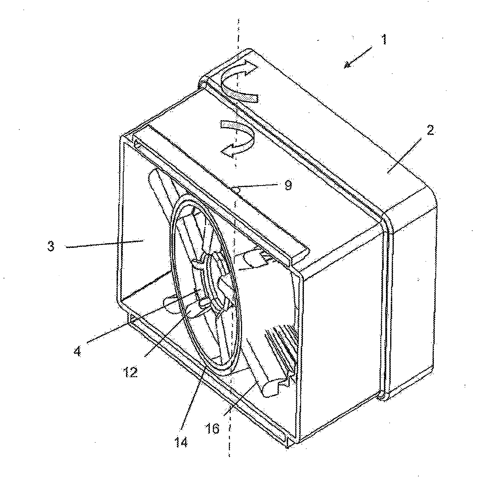
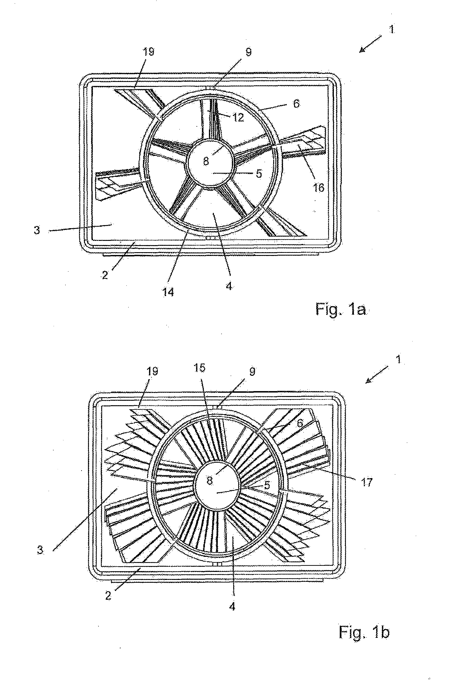
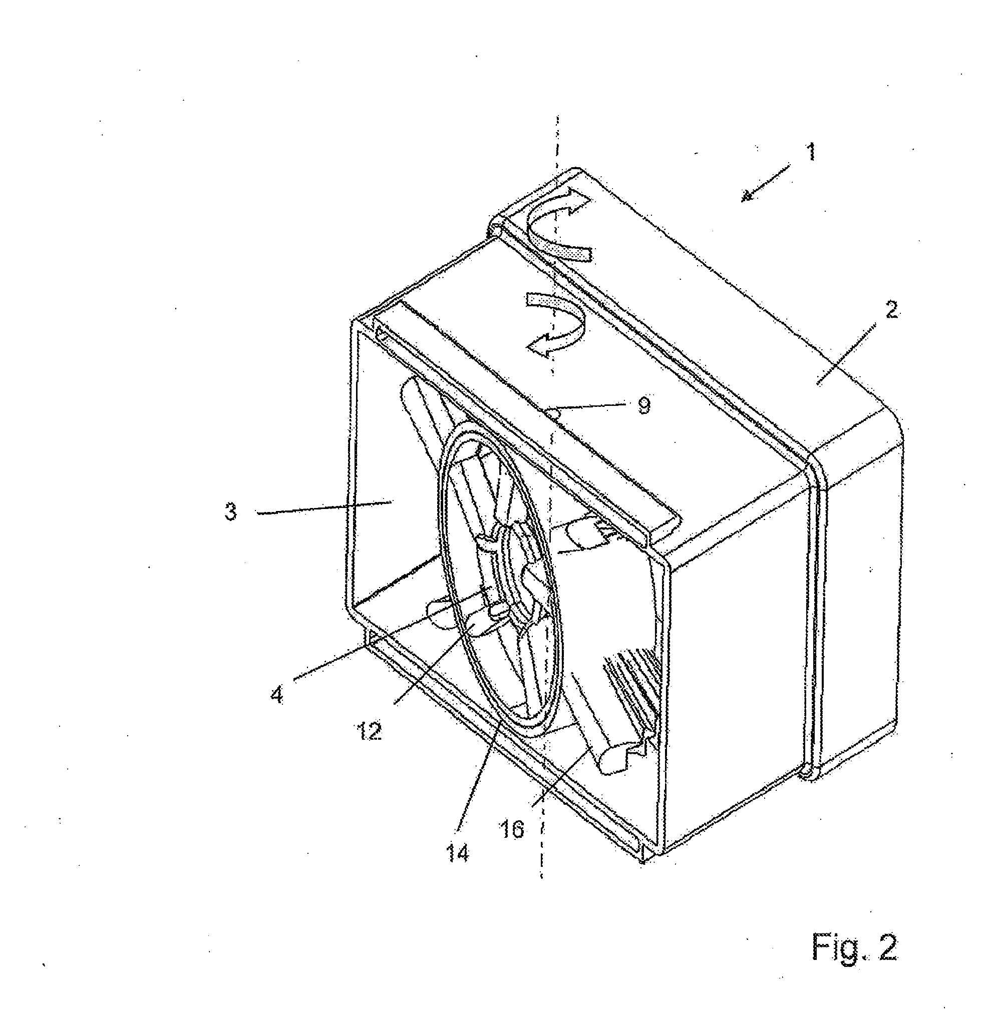
[0034]In the two drawings of FIG. 1, in each case a comfort air vent nozzle 1 is shown each in different positions in a schematic plan view. In this case, the position of comfort air vent nozzle 1, shown in FIG. 1a, corresponds to an operating position in which comfort air vent nozzle 1 provides a directed air jet (so-called spot discharge operation). In FIG. 1b, in contrast, an operating position of comfort air vent nozzle 1 is shown in which comfort air vent nozzle 1 releases a diffuse airflow.

[0035]Comfort air vent nozzle 1 is typically installed in the area of the dashboard of a motor vehicle. Comfort air vent nozzle 1 is generally used for ventilating the head region or the chest region of the vehicle passengers, particularly the front passengers of a motor vehicle. Here, the problem occurs that some passengers would like to be “blown at” with a rather directed air jet, whereas other passengers prefer a diffuse airflow. In part, these individual preferences also change dependin...


PUM


Abstract

An air discharging device for discharging an air flow into a vehicle interior is provided that includes a first air conducting device that can be adjusted with respect to the air discharging characteristic thereof, the air conducting device lying in a first air through-flow region of the air discharging device. The air discharging device also includes a second air conducting device that can be adjusted with respect to the air discharging characteristic thereof, the air conducting device lying in a second air through-flow region of the air discharging device.

Description

[0001]This nonprovisional application is a continuation of International Application No. PCT / EP2010 / 070643, which was filed on Dec. 23, 2010, and which claims priority to German Patent Application No. DE 10 2010 004 021.5, which was filed in Germany on Jan. 4, 2010, and which are both herein incorporated by reference.BACKGROUND OF THE INVENTION[0002]1. Field of the Invention[0003]The present invention relates to an air discharging device for discharging an air stream, particularly into a vehicle interior, with at least one air conducting device, which is adjustable at least with respect to its air discharging characteristics and which is disposed in at least one first air discharge region of the air discharging device.[0004]2. Description of the Background Art[0005]During the ventilation of closed interior spaces, such as, for example, of motor vehicles, air is drawn in very generally at one or at a number of places, processed, and delivered into the interior space to be ventilated....

Claims


Application Information

Patent Timeline
IPC IPC(8): B60H1/34
CPCB60H1/3457
Inventor WOLF, WALTERBENAMIRA, SALAHD'ANGELO, MARCOTIDELSKI, AXELZELLER, KUNOFRITSCHE, UWEWANKE, HOLGER
Owner MAHLE INT GMBH
Learn More