Mold for molding a tire

Inactive Publication Date: 2004-11-16
NGK INSULATORS LTD
View PDF16 Cites 23 Cited by
  • Summary
  • Abstract
  • Description
  • Claims
  • Application Information

AI Technical Summary

Problems solved by technology

This is a problem when air bubble defects, such as air inclusions, are produced.
Depending on the mold, this cleaning and the like can become troublesome, requiring the introduction of long cleaning times and expensive equipment.
This results in a problem that production costs of the articles produced increase.
There is a disadvantage in that the external appearance and initial running performance of the molded tire are deteriorated.
The occurrence of spew can be prevented when a non-spew or slit vent type means is employed, however, it cannot prevent the formation of burred extensions.
Further, in the case of this type of a mold, not only is the production cost of a mold expensive, but also there is a disadvantage in that clogging during molding occurs readily in addition to being more expensive.
Thus, it requires several man-hours for cleaning by blasting.
Further, since slit portions clog readily with repeated blasting and the contaminants accumulated in slit portions are difficult to remove, special cleaning methods such as chemical cleaning and plasma cleaning should be used.
This requires long cleaning times and the introduction of expensive equipment.
This is a disadvantage in that the production costs of the molded item increase.
That is, at present, a mold equipped with a non-spew type means is used when a serious consideration must be given to the external appearance and the initial performance of a tire, with the acceptance of a relatively expensive production cost.
On the other hand, however, a mold equipped with a venthole type means is used when a serious consideration must be given to the production costs of a mold and the running costs in t

Method used


Image

  • Mold for molding a tire
  • Mold for molding a tire
  • Mold for molding a tire

Examples


Example

Embodiment 1

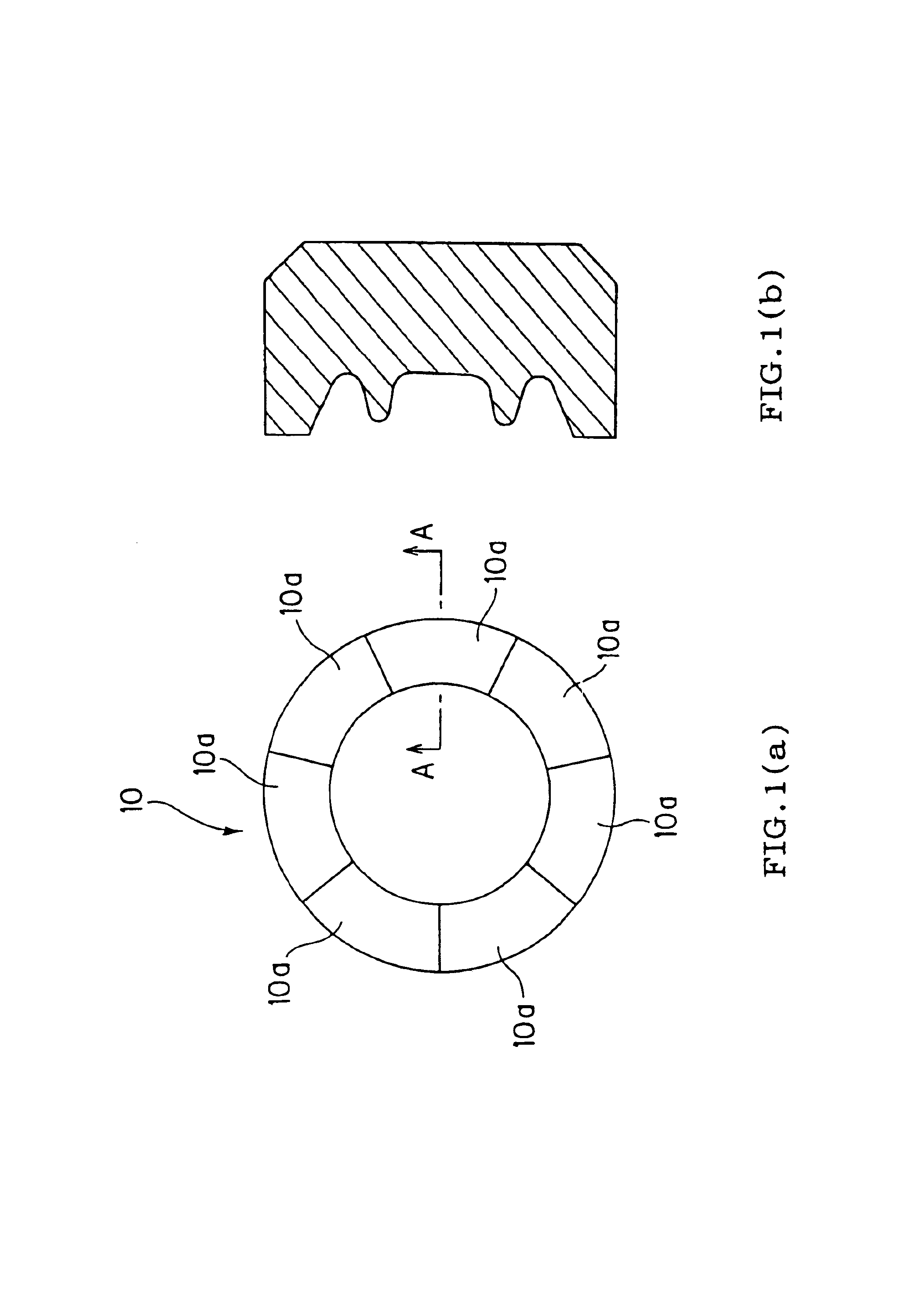
A mold divided into 7 units (a configuration of 1 set of a complete mold with 7 sub-molds 10(a) along the circumference using segmented molds as shown in FIGS. 1(a) and 1(b) are produced via aluminum alloy casting methods (plaster casting methods) (material: foam plaster and aluminum alloy material AC4C (Si 7%, Cu 0.8%, Mg 0.4%, and Al as the remainder) using a plaster cast. In this event, the initial setting for the number of individual ventholes is 1376 per set.

Next, into a sub-mold 200a where a venthole 201 and a counterboring 205 as shown in FIG. 34(a) are formed via machining with the production process is inserted as shown in FIGS. 34(d) to 34(f) a positioning tube 204 (material: SUS304) as shown in FIGS. 34(a) to 34(f) and a ventlid 202 (material: SUS304) having a lid 203 as shown in FIG. 34(b). In this event, the positioning tube 204 is provided by caulking in a sub-mold 200a (FIG. 34(d)), the ventlid 202 is put in place on top of the positioning tube 204 (FIG. 3...

Example

Embodiment 2

As shown in FIGS. 35(a) to 35(c), a mold for molding a tire as indicated in Embodiment 1 was produced in the same manner as Embodiment 1 with the exception of changing the depth of the counterboring 205 of the sub-mold 200a to 3.10 mm, the diameter of the lid 203 of the ventlid 202 to 2.0 mm, and the tab thickness to 0.1 mm.

With continuous molding of a tire using a mold produced in this manner, air inclusion defects did not occur and a tire was formed with almost no burrs in the lid portion of the ventlid.

Further, concave impressions in locations corresponding to the lid portion of the ventlid in the tire in this event fell below 0.05 mm and a satisfactory external appearance and quality in comparison to Embodiment 1 were obtained.

Further, maintenance of the air removal characteristics was confirmed even after continuous molding of 20000 tires.

Example

Embodiment 3

As shown in FIGS. 36(a) to 36(d), a mold for molding a tire as indicated in Embodiment 1 was produced in the same manner as Embodiment 1 with the exception of changing the shape of the counterboring 205 of the sub-mold 200a to an undercut by cast removal and production of the shape of the ventlid 202 as shown in FIG. 36(b) with an additive silicon rubber (Toray Silicone, brand name: SH9555).

In this event as shown in FIGS. 36(c) to 36(d), the ventlid 202 was inserted in a sub-mold 200a using an undercut. With continuous molding of a tire using a mold produced in this manner, air inclusion defects did not occur and a tire was formed with almost no burrs in the lid portion of the ventlid.

Further, there were almost no concave impressions in locations corresponding to the lid portion of the ventlid in the tire in this event. Further, maintenance of the air removal characteristics was confirmed even after continuous molding of 20000 tires.


PUM

PropertyMeasurementUnit
Angleaaaaaaaaaa
Angleaaaaaaaaaa
Flexibilityaaaaaaaaaa

Abstract

A mold for molding a tire is provided, including at least two sub-molds that form a predetermined form as a whole when used for molding a tire. Each of the sub-molds has a venthole for discharging air from blockades formed between the surface of a green tire and that of the sub-mold when the green tire is pressed on the surface of the sub-mold, and a ventlid made of a flexible member and having a lid mechanism capable of discharging air from the blockades while preventing the green tire from flowing out therefrom.

Description

(1) Field of the InventionThe present invention relates to a mold for molding a tire. More particularly, the present invention relates to a mold for molding a tire to prevent spew (whisker projections) and burred extensions on a tire surface during tire molding, to allow the retention of the initial performance of a tire obtained and good external appearance, and to allow designing for reduction in the number of molds and their production costs as well as simplification of maintenance and inspection work.(2) Related Art StatementThe molds for molding a tire are often manufactured by means of casting which fits for the forming of complicated shapes conforming to the surface shape designed as complicated shapes having numerous thin projections termed sharp corners or blades for a tire.Molds for molding a tire manufactured by means of this casting are ordinarily divided into sub-molds, and these sub-molds are combined to form a predetermined form as a whole at the time of forming a tir...

Claims


Application Information

Patent Timeline
IPC IPC(8): B29D30/06B29C33/02B29C33/10B29C35/02B29K19/00B29K21/00B29K105/24B29L30/00
CPCB29D30/0606Y10S425/812B29D2030/0617
Inventor ISHIHARA, YASUYUKI
Owner NGK INSULATORS LTD
Why Eureka
Try Eureka