Palatal T-Bar

a t-bar and palatal technology, applied in the field of palatal t-bars, can solve the problems of high cost and significant healing time of dental implants, and achieve the effect of preventing movement of selected teeth

Active Publication Date: 2013-03-14
CARRILLO FUENTEVILLA ROBERTO +1
View PDF8 Cites 4 Cited by
  • Summary
  • Abstract
  • Description
  • Claims
  • Application Information

AI Technical Summary

Benefits of technology

[0007]A palatal t-bar for preventing movement of selected teeth during corrective movement of other teeth through the use of an orthodontic appliance such as orthodontic braces is provided. The t-bar comprises an elongate stem having an anchorage end arranged for affixation to the palatal bone of a patient by means of a temporary bone anchorage device, e.g., a miniscrew implant, and a free end extending in an anterior direction from the anchorage end. The stem is shaped to conform to the palatal surface of the patient. A cross-bar extends laterally from the free end of the stem and is arranged to engage one or more selected maxillary anterior teeth to retain the teeth non-mobile and non-rotational during corrective movement of other teeth utilizing an orthodontic appliance such as orthodontic braces.

Problems solved by technology

However, often these attempts are expensive, or involve surgery typically requiring significant healing time.

Method used


Image

  • Palatal T-Bar
  • Palatal T-Bar
  • Palatal T-Bar

Examples


Embodiment Construction

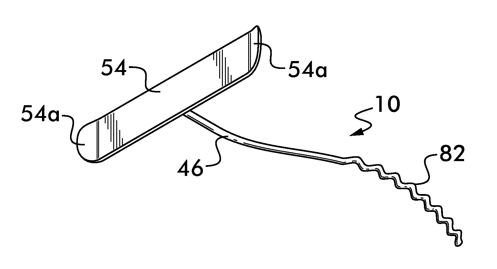
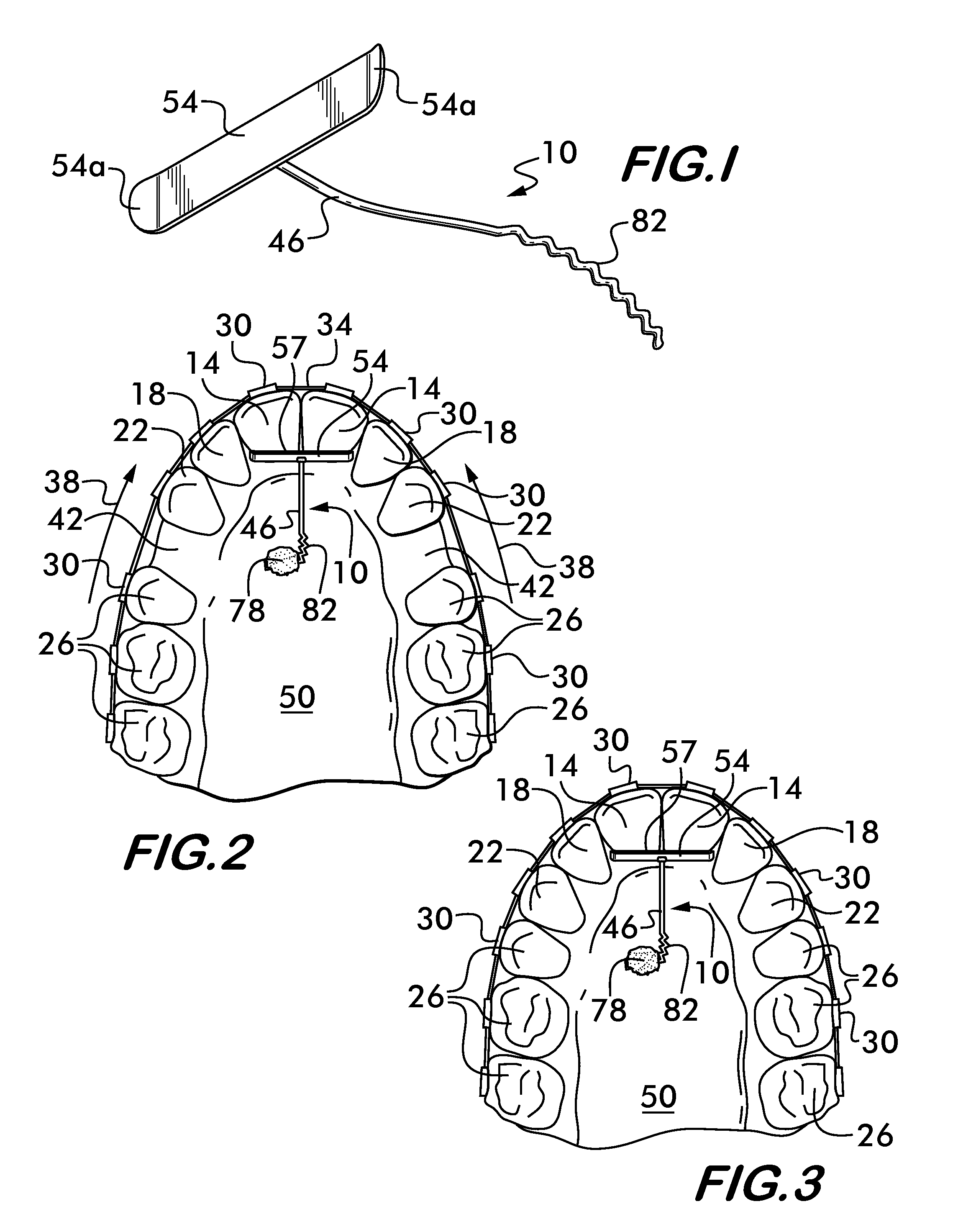
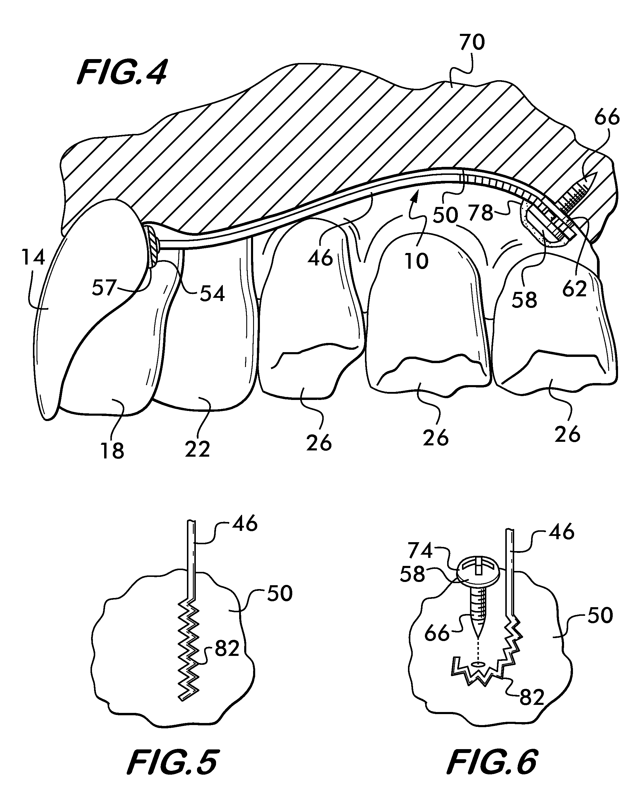
[0016]Referring now in greater detail to the drawings in which like numerals represent like components throughout the several views, FIGS. 1-4 illustrate a first preferred embodiment of the palatal t-bar 10 of the present invention. As best shown in these figures, the palatal t-bar 10 is intended for placement within the mouth of a patient to serve as an anchorage to prevent one or more selected teeth (as an example here shown on teeth 14) anchored within the t-bar 10 from rotating, torquing, or moving distally during corrective movement of other teeth. Such other teeth may include lateral incisors 18, canines 22, or posterior teeth 26. As shown in FIGS. 1-4, corrective movement of teeth 14, 18, 22, and 26 is shown as being accomplished utilizing orthodontic braces, wherein brackets 30 are bonded to teeth 14, 18, 22, and 26 and an arch wire 34 is attached to the brackets 30 in known ways. The arch wire 34 exerts pressure on the brackets 30 and teeth 14, 18, 22, 26 whereby the positi...


PUM


Abstract

A palatal t-bar for preventing movement of selected teeth during corrective movement of other teeth through the use of an orthodontic appliance such as orthodontic braces. The t-bar comprises an elongate stem having an anchorage end arranged for affixation to the palatal bone of a patient by means of a temporary bone anchorage device, e.g., a miniscrew implant, and a free end extending in an anterior direction from the anchorage end. The stem is shaped to conform to the palatal surface of the patient. A cross-bar extends laterally from the free end of the stem and is arranged to engage one or more selected maxillary anterior teeth to retain the teeth non-mobile and non-rotational during corrective movement of other teeth utilizing an orthodontic appliance such as orthodontic braces.

Description

CROSS-REFERENCE TO RELATED APPLICATIONS[0001]“Not Applicable”STATEMENT REGARDING FEDERALLY SPONSORED RESEARCH OR DEVELOPMENT[0002]“Not Applicable”INCORPORATION-BY-REFERENCE OF MATERIAL SUBMITTED ON A COMPACT DISK[0003]“Not Applicable”FIELD OF THE INVENTIONBackground of the Invention[0004]To clarify the description of the invention, certain dental terms should be understood. Upper and lower teeth are termed maxillary and mandibular teeth, respectively. Front teeth are anterior teeth and back teeth are posterior teeth. Anterior teeth are incisors and are named centrals, laterals, and cuspids in order from the anterior midline to the posterior. The posterior teeth, from anterior to posterior, are first and second premolars and first, second, and third molars. Distal refers to the direction towards the last posterior tooth, as opposed to mesial, which refers to the direction towards the anterior midline.[0005]Orthodontists and dental researchers are constantly searching for new and impr...

Claims


Application Information

Patent Timeline
Patent Type & Authority Applications(United States)
IPC IPC(8): A61C7/00
CPCA61C8/0096A61C7/00B33Y80/00
Inventor CARRILLO FUENTEVILLA, ROBERTOGONZALEZ, ROBERTO JOSE CARRILLO
Owner CARRILLO FUENTEVILLA ROBERTO
Why Eureka
Try Eureka