Antenna apparatus for portable terminal

a portable terminal and antenna technology, applied in the direction of resonant antennas, elongated active element feeds, independent non-interacting antenna combinations, etc., can solve the problems of performance degradation and disrupt the performance of the portable terminal, and achieve the effect of reducing mutual interferen

Inactive Publication Date: 2013-03-21
SAMSUNG ELECTRONICS CO LTD
View PDF3 Cites 77 Cited by
  • Summary
  • Abstract
  • Description
  • Claims
  • Application Information

AI Technical Summary

Benefits of technology

[0005]To address the above-discussed deficiencies of the prior art, it is a primary object to provide at least the advantages described below. Accordingly, an aspect of the present disclosure is to provide an antenna apparatus for a portable terminal capable of reducing mutual interference even if antennas are not placed to be spaced apart from each other.

Problems solved by technology

However, since several antennas are provided in a limited space, interference may occur between the antennas, which results in a problem of performance deterioration. FIG. 1 illustrates a perspective view of a conventional antenna apparatus.
However, as illustrated, if the two antennas 120 and 130 are located close to each other, the two antennas 120 and 130 mutually interfere with each other, and disrupt the performance of the portable terminal.

Method used


Image

  • Antenna apparatus for portable terminal
  • Antenna apparatus for portable terminal
  • Antenna apparatus for portable terminal

Examples


Embodiment Construction

[0017]FIGS. 1 through 13, discussed below, and the various embodiments used to describe the principles of the present disclosure in this patent document are by way of illustration only and should not be construed in any way to limit the scope of the disclosure. Exemplary embodiments of the present disclosure will be described herein below with reference to the accompanying drawings. In the following description, well-known functions or constructions are not described in detail since they would obscure the disclosure in unnecessary detail. Also, the terms used herein are defined according to the functions of the present disclosure. Thus, the terms may vary depending on user's or operator's intension and usage. That is, the terms used herein are to be understood based on the descriptions made herein.

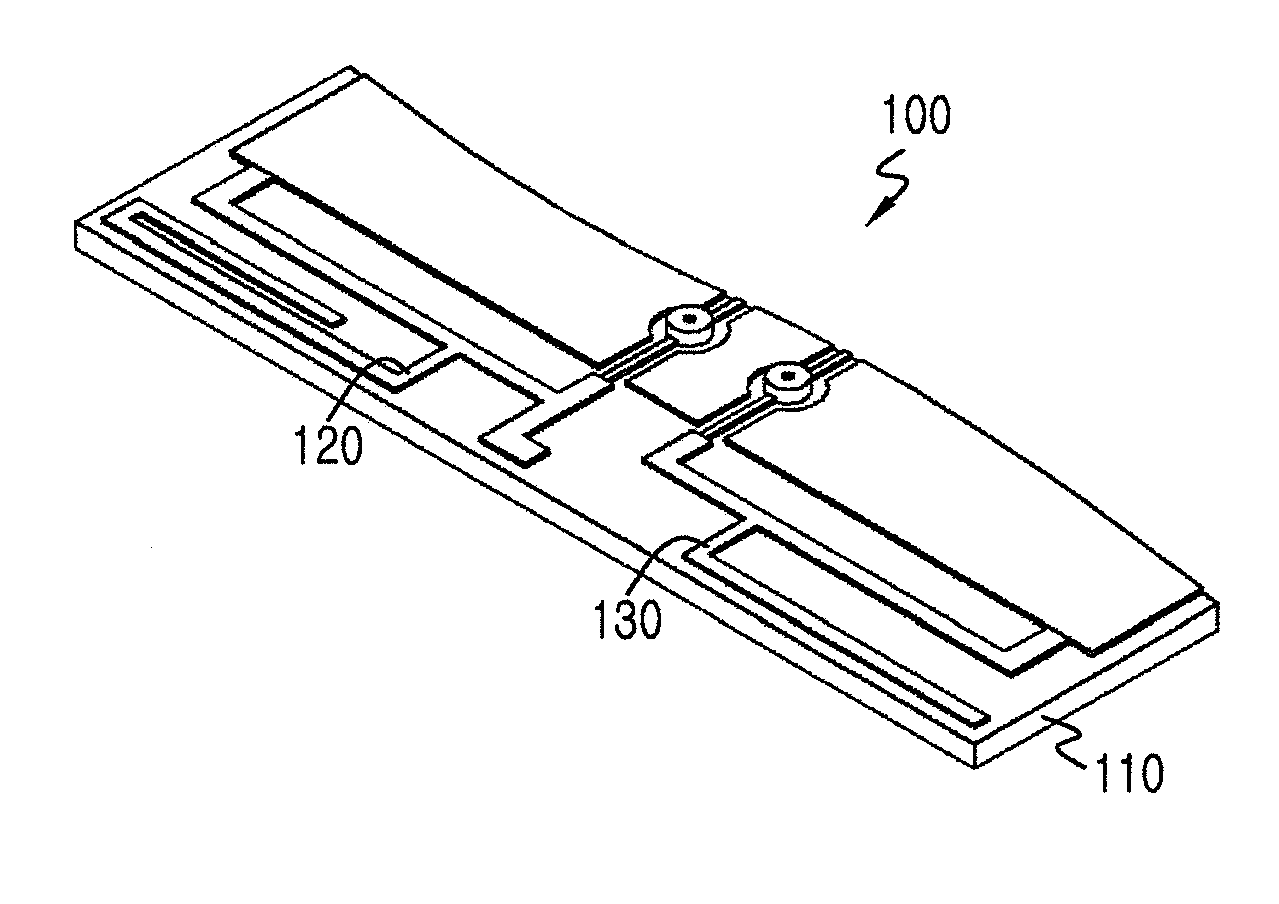
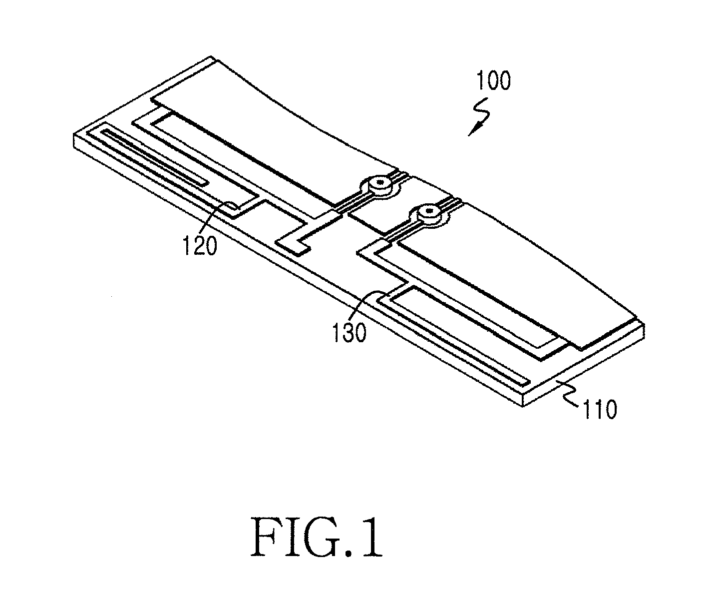
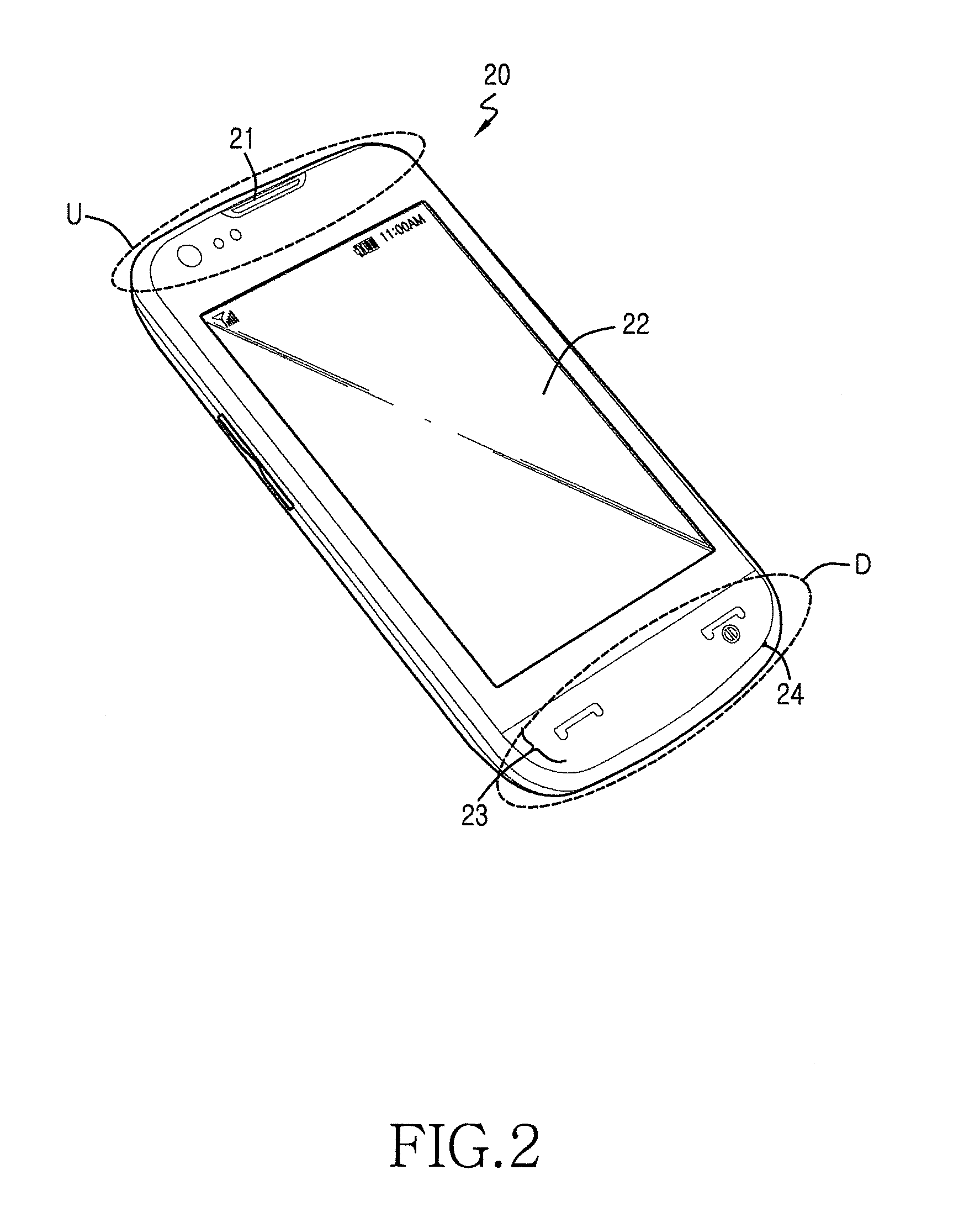
[0018]The present disclosure relates to an antenna apparatus for a portable terminal capable of improving an isolation between antennas. The antenna apparatus of the present disclosure doe...


PUM


Abstract

An antenna apparatus for a portable terminal is configured to reduce interference. The antenna apparatus includes a first antenna and a second antenna spaced apart from the first antenna. The antenna apparatus also includes a filter coupled to the first antenna and the second antenna, and configured to increase an isolation between the first antenna and the second antenna by filtering signals transmitted through the first antenna and the second antenna. The antenna apparatus further includes a main board configured to process the filtered signals.

Description

CROSS-REFERENCE TO RELATED APPLICATION AND CLAIM OF PRIORITY[0001]The present application is related to and claims the benefit under 35 U.S.C. §119(a) of a Korean patent application filed in the Korean Intellectual Property Office on Sep. 20, 2011 and assigned Serial No. 10-2011-0094642, the entire disclosure of which is hereby incorporated by reference.TECHNICAL FIELD OF THE INVENTION[0002]The present disclosure relates to an antenna apparatus for a portable terminal.BACKGROUND OF THE INVENTION[0003]With the development of electronics communication industries in recent years, a portable terminal has become a necessity of modern life as an important means for delivering information which changes rapidly. Therefore, the portable terminal is developed competitively by those skilled in the art to ensure more users. Further, since a communication service such as Global System for Mobile Communications (GSM), Personal Communications Services (PCS), Digital Multimedia Broadcasting (DMB), ...

Claims


Application Information

Patent Timeline
Patent Type & Authority Applications(United States)
IPC IPC(8): H01Q21/28
CPCH01Q21/28H01Q1/243H01Q5/371H01Q9/42H01Q1/521H01Q1/24H01Q1/52H01Q13/08
Inventor LEE, SEUNG-JUNSEO, JAE-MINPARK, SUNG-WONPARK, JAE-SUN
Owner SAMSUNG ELECTRONICS CO LTD
Why Eureka
Try Eureka