High power data line connection

a high-power data line and connection technology, applied in the direction of electrical equipment, basic electric elements, coupling device connections, etc., can solve the problems of insufficient solution of connecting sockets, particularly severe interference between the pairs b>4/b>/b>5/b>, etc., to reduce electrical interference and reduce electrical interference.

Inactive Publication Date: 2005-01-11
SETEC NETZWERKE
View PDF14 Cites 37 Cited by
  • Summary
  • Abstract
  • Description
  • Claims
  • Application Information

AI Technical Summary

Benefits of technology

The above and over objects and advantages of the invention are achieved by the provision of a data line connection which comprises a base printed circuit board, a female connector mounted to the base printed circuit board, and a compensation printed circuit board mounted within the female conne

Problems solved by technology

The requirements for classes 5, 5e and 6 can be satisfied relatively well at the moment for cables, but no satisfactory solution exists for connecting sockets, particularly those in category 6.
Because of this physical arran

Method used


Image

  • High power data line connection
  • High power data line connection
  • High power data line connection

Examples


Embodiment Construction

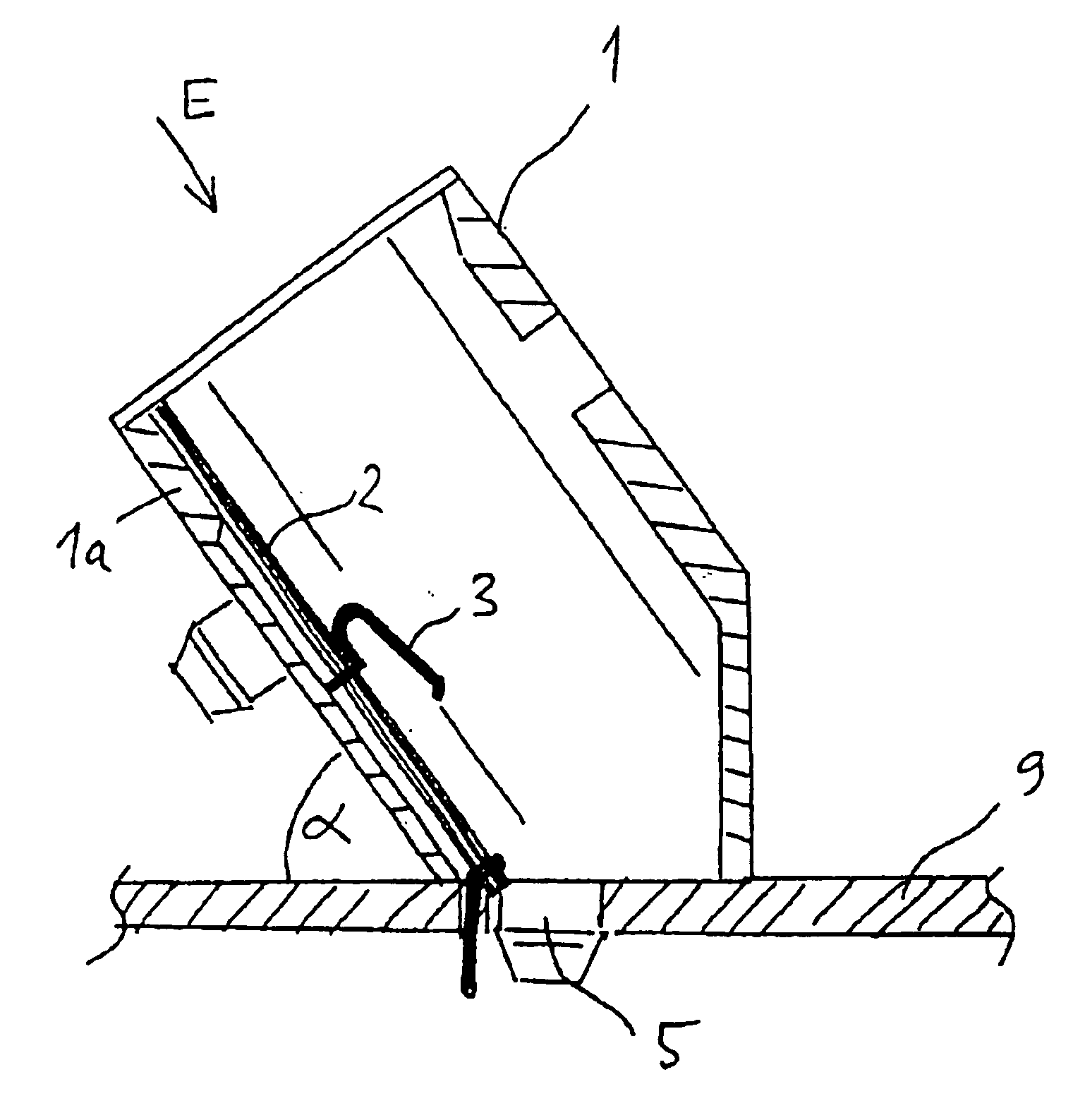
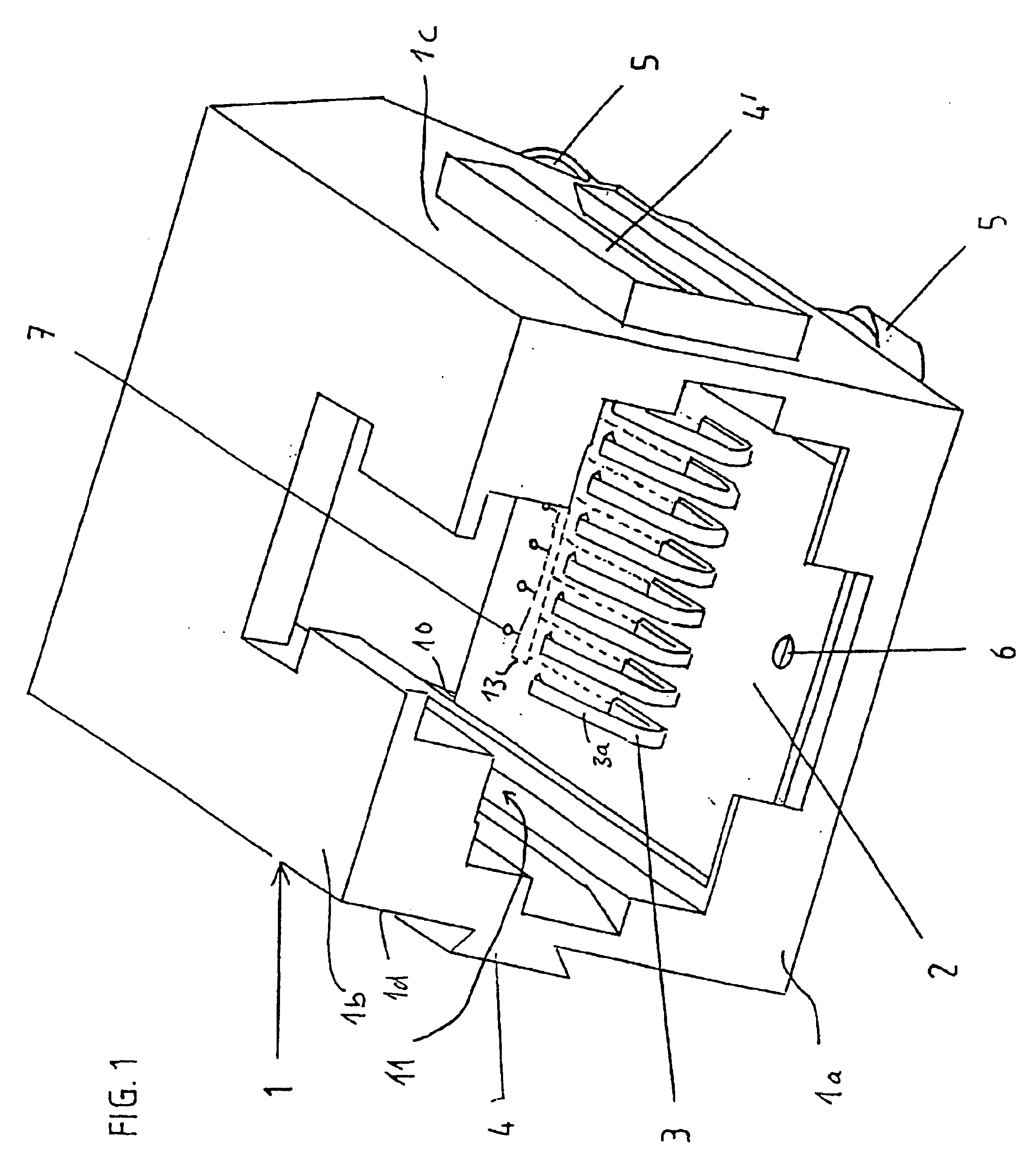
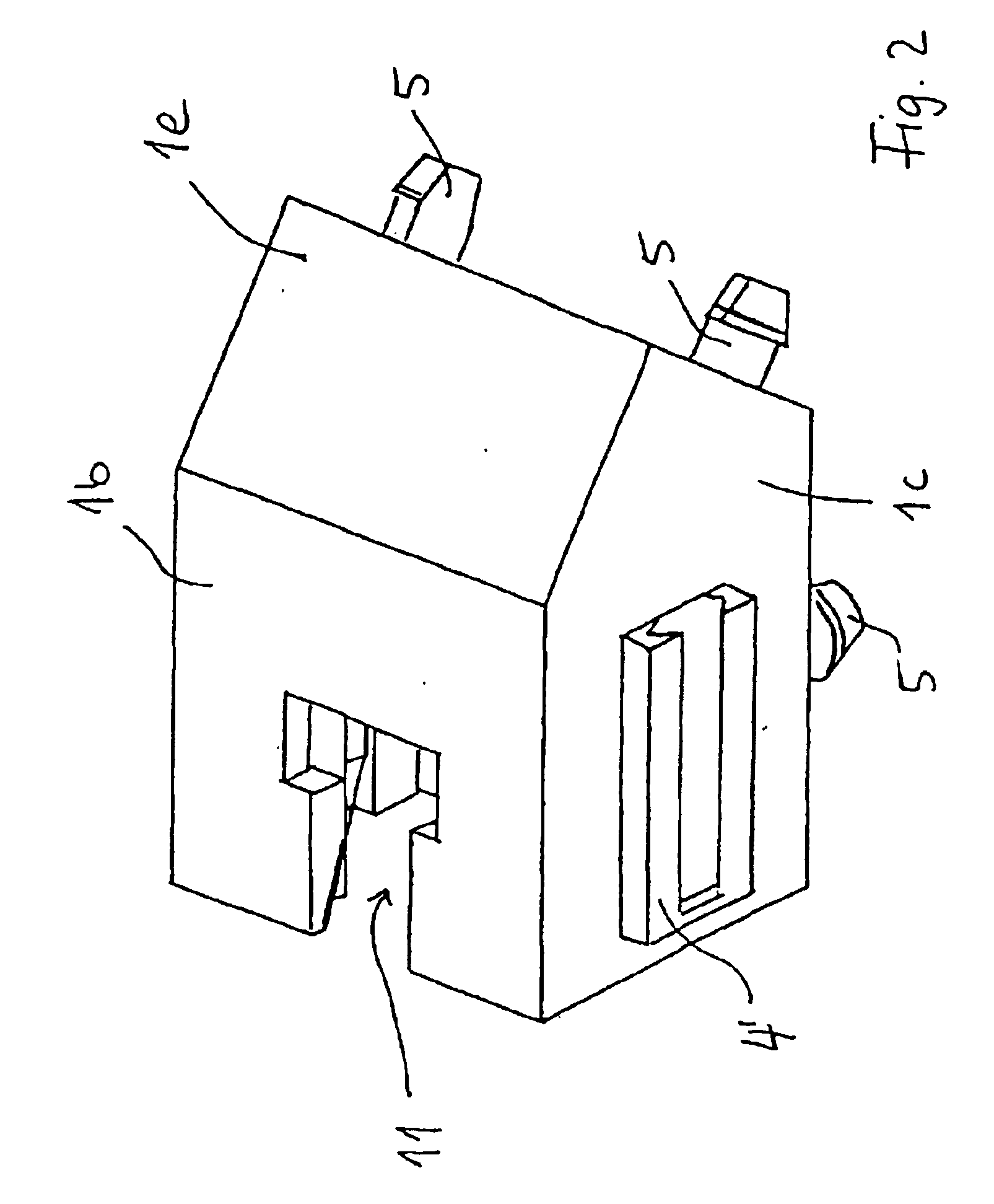
FIGS. 1 and 2 show two three-dimensional views of a female connector according to the invention with a holding element 1 which forms a holder 11 with the same shape as conventional RJ45 female connectors, for a plug. FIGS. 3 and 4 show two different installation positions of this female connector on a base printed circuit board 9.

The holding element 1 has an essentially cuboid basic shape with a bottom surface 1a and top surface 1b, and two parallel side surfaces 1c, 1d. The rearward area 1e in the present case is inclined or designed in a prism shape, in order to make it possible to mount the connecting element on a base printed circuit board in various installation positions (FIGS. 3 and 4).

The compensation printed circuit board 2 according to the invention is arranged within the holding element 1, in this case in the area of the bottom surface 1a. The compensation printed circuit board 2 can, where appropriate, replace the bottom surface 1a. Sprung contact elements 3 which are be...


PUM


Abstract

A data line connection which comprises a base printed circuit board, a female connector mounted to the base printed circuit board, and a compensation printed circuit board mounted within the female connector. The compensation printed circuit board mounts a plurality of electrically conductive contact elements as well as a compensation circuit for reducing electrical interference. The base printed circuit board includes a further compensation circuit for further reducing electrical interference.

Description

BACKGROUND OF THE INVENTIONThe invention relates to a female connector and connecting socket for producing a high-power data line connection to such a female connector.In order to produce a data line connection from a server to a terminal (channel) or between the corresponding connecting socket (link) with a high data transmission capacity, all the components of the channel or link, in particular the data cables and connecting sockets, have to satisfy specific minimum requirements relating to their transmission characteristics. The components are subdivided on the basis of their transmission characteristics into various categories of which, at the moment, categories 5, 5e and 6 are of particular interest. It is planned to standardize the specifications for components in the relevant categories. On the basis of a standardization proposal such as this, cables in categories 5, 5e and 6 have to suppress the near end crosstalk or NEXT by 32.3, 35.3 or 44.3 dB at 100 MHz. For connecting s...

Claims


Application Information

Patent Timeline
IPC IPC(8): H01R13/66H01R13/514H01R24/00H01R24/58
CPCH01R13/6658H01R13/6466Y10S439/941H01R24/64H01R2107/00
Inventor EBERLE, ANDREASNEFF, FRANZDAUBA, HERBERT
Owner SETEC NETZWERKE
Why Eureka
Try Eureka