Eureka AIR delivers breakthrough ideas for toughest innovation challenges, trusted by R&D personnel around the world.

Control system for wind turbines for reducing disturbances in an electrical grid

a technology of control system and wind turbine, which is applied in the direction of motors, dynamo-electric machines, engine fuction, etc., can solve the problem of restricting the control action of damping controllers

Active Publication Date: 2019-07-30
VESTAS WIND SYST AS
View PDF15 Cites 3 Cited by
  • Summary
  • Abstract
  • Description
  • Claims
  • Application Information

AI Technical Summary

Benefits of technology

[0005]It is a further object of the invention to reduce electrical disturbances in the grid which are caused by wind turbines.
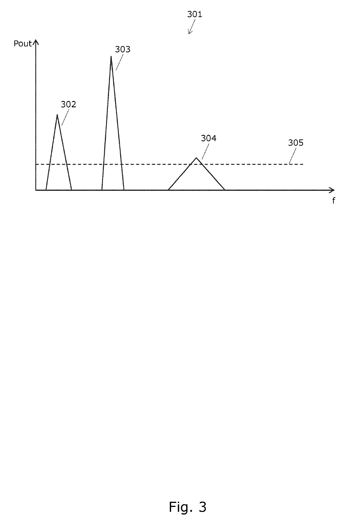
[0016]It should be noted that the present invention is particularly advantageous when a plurality of wind turbines, e.g. a so-called ‘wind park’ or ‘wind farm’, is controlled according to the invention because combined oscillations of the wind turbines are normally not in phase, and therefore the combined contribution of these oscillation to the electrical disturbance in the grid could be lower than the simple sum, but nevertheless there may be a significant electrical disturbance worth reducing with the present invention by measuring in, or near, the electrical grid, particular in, or near, the point of connection (PoC) between the plurality of wind turbines and the electrical grid.

Problems solved by technology

Advantageously, the control action performed by damping controllers may be restricted dependent on measured disturbance information determined from measured power at a point of measurement.

Method used


Image

  • Control system for wind turbines for reducing disturbances in an electrical grid
  • Control system for wind turbines for reducing disturbances in an electrical grid
  • Control system for wind turbines for reducing disturbances in an electrical grid

Examples


Embodiment Construction

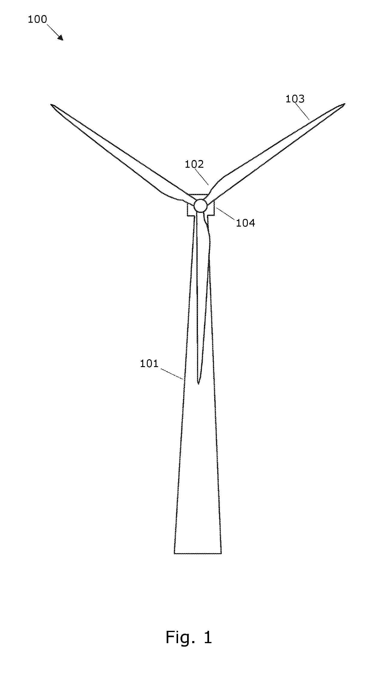
[0046]FIG. 1 shows a wind turbine 100 comprising a tower 101 and a rotor 102 with at least one rotor blade 103, such as three blades. The rotor is connected to a nacelle 104 which is mounted on top of the tower 101 and being adapted to drive a generator situated inside the nacelle. The rotor 102 is rotatable by action of the wind. The wind induced rotational energy of the rotor blades 103 is transferred via a shaft to the generator. Thus, the wind turbine 100 is capable of converting kinetic energy of the wind into mechanical energy by means of the rotor blades and, subsequently, into electric power by means of the generator. In this document the wind turbine 100 may also be referred to with the common abbreviation WTG (Wind Turbine Generator).

[0047]According to an embodiment, the wind turbine 100 may be configured so that the torque on the shaft and / or the electric power produced by the generator can be controlled via a control input to the generator, e.g. via a control input to a ...


PUM


Abstract

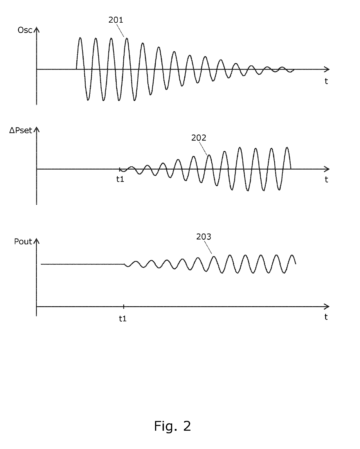
The invention relates to a method for wind turbine generators for reducing electrical disturbances in the form of power variations which are caused by damping controllers arranged the compensate structural oscillations by inducing shaft torque variations. The shaft torque variations are generated by imposing corresponding variations in a generator set-point, e.g. a power or torque set-point. Variations in the generator set-point cause undesired variations in the power injected to the grid by one or more wind turbine generators. According to an embodiment of the invention the electrical disturbances may be reduced by limiting a damping controller's control action. The amount of limitation or restriction of the damping controller may be determined on basis on electrical disturbance information determined from power measured e.g. at a location on the grid.

Description

FIELD OF THE INVENTION[0001]The invention relates to control of at least one wind turbine, particularly to controlling a damping controller of one or more wind turbines.BACKGROUND OF THE INVENTION[0002]Structural oscillations in wind turbines caused e.g. by the wind may be damped actively by generating counteracting oscillations. Such counteracting oscillations may be generated by inducing variations in the shaft torque, e.g. by varying a power or torque set-point for the generator of the wind turbine. The variations may be generated by a damping controller.[0003]In order to improve performance of the wind turbine there is a need to improve control of damping controllers.SUMMARY OF THE INVENTION[0004]It is an object of the invention to improve the control of a wind turbine in relation to damping of a wind turbine.[0005]It is a further object of the invention to reduce electrical disturbances in the grid which are caused by wind turbines.[0006]In a first aspect of the invention there...

Claims


Application Information

Patent Timeline
Patent Type & Authority Patents(United States)
IPC IPC(8): F03D7/02F03D7/04H02K7/18H02P9/04
CPCF03D7/0284F03D7/0296F03D7/048H02K7/183H02P9/04Y02E10/723F05B2260/96F05B2260/964F05B2270/334F05B2270/337Y02E10/72
Inventor KJ.AE BUTTED.R, MARTIN ANSBJERGCAPONETTI, FABIOCOUCHMAN, IANTHOMSEN, JESPER SANDBERGKRUGER, THOMASGARCIA, JORGE MARTINEZ
Owner VESTAS WIND SYST AS
Why Eureka
Eureka Blog
Learn More