Antenna and electric device with antenna

An electrical equipment and antenna technology, applied in the field of antennas and electrical equipment with the antenna, can solve the problems of high manufacturing cost of portable terminals and electrical equipment, and the inability to use antennas, so as to suppress transmission loss, improve integration characteristics, and shorten path lengths Effect

Inactive Publication Date: 2009-02-04
HITACHI CABLE
View PDF3 Cites 3 Cited by
  • Summary
  • Abstract
  • Description
  • Claims
  • Application Information

AI Technical Summary

Problems solved by technology

[0008] As mentioned above, although it is easy to install the antenna in the casing of the portable terminal and the electric equipment in the prior art, since the transmission and reception of the digital signal wave, especially the reception, the necessary monitoring of the electrical interference existing in the casing is not carried out. Therefore, there is a possibility that it cannot be used as a transmitting and receiving antenna corresponding to digital signal waves mainly in digital broadcasting
[0009] Moreover, although it is the best method to use the portable terminal and the electric equipment itself to implement the countermeasure of the electrical interference in the box, it is also possible that the cost of manufacturing the portable terminal and the electric equipment itself will be expensive due to this countermeasure, so it is desirable Using these one-part antennas, it is possible to improve countermeasures against electrical interference that is a problem with a simpler and more versatile method

Method used


Image

  • Antenna and electric device with antenna
  • Antenna and electric device with antenna
  • Antenna and electric device with antenna

Examples


Embodiment 3

[0236] Figure 25 expressed in Figure 13 The ground portion of the panel antenna 201 shown is connected to the panel antenna 221 of the soft conductor sheet 131 . The flat panel antenna 221 is electrically connected to the flexible conductor sheet 131 on the ground 7, which is used as a part of the ground. Moreover, this construct is also compatible with Figure 21 The panel antenna shown is also an example of a method of enlarging the ground wire in consideration of the characteristics of the antenna itself. In addition, the electrical connection between the flexible conductor sheet 131 and the ground wire 7 is performed by connecting the two with solder (not shown) or conductive tape (not shown), or by providing an electrical connection structure (not shown), Regardless of the electrical connection method, the same effect can be obtained.

[0237] Figure 26 expressed in Figure 15 The LCD box is built with a Figure 25 The structure of the LCD box of the panel anten...

Embodiment 4

[0241] Figure 28 Indicates that it will be with Figure 13 The panel antenna 201 shown in the same antenna image is the panel antenna 231 fabricated on the dielectric substrate 141 . The panel antenna 231 has an antenna pattern formed of a conductor, and has a threaded through hole 10 for elastic fixing.

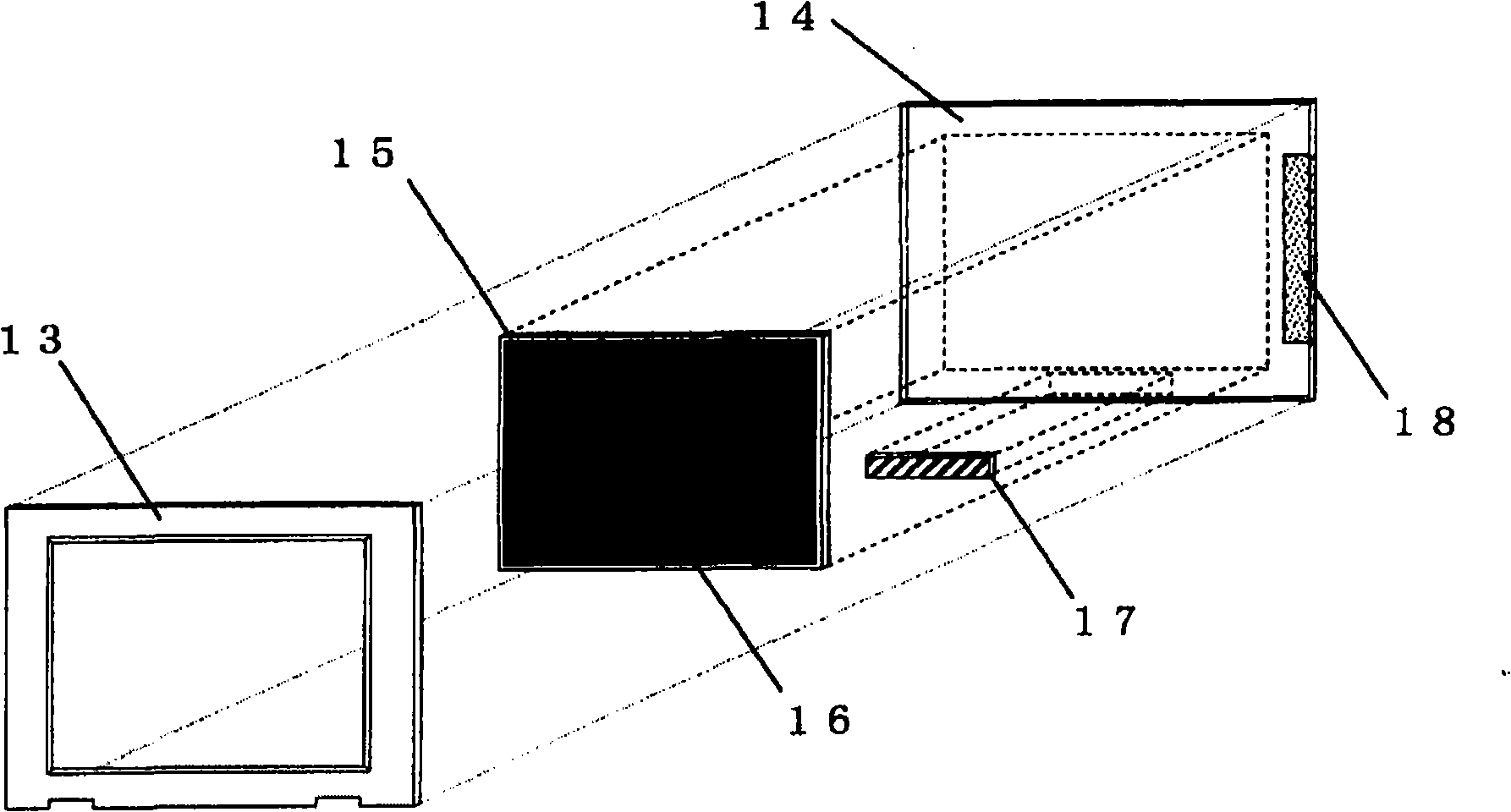
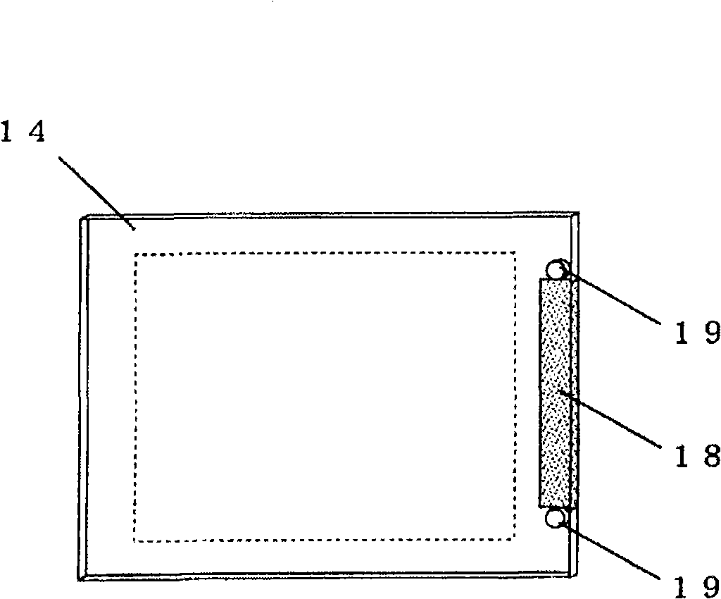
[0242] Figure 29 expressed in Figure 15 The LCD box is built with a Figure 28 The state inside the LCD box when the panel antenna 231 is in place. Figure 29 (a) Remove the front cover 13 of the LCD box, and squint at the fixed state with the flat panel antenna 231 inside, Figure 29 (b) means Figure 29 The cross-sectional structure between the dotted line Aa in (a). In addition, a coaxial cable (not shown) is connected to the feeding point of the panel antenna 231, and the coaxial cable is arranged inside the LCD box in consideration of the influence of electric noise.

[0243] In this embodiment, too, the intrusion of electrical interference to the antenna can...

Embodiment 5

[0245] Figure 30 expressed in Figure 28 The ground wire 7 of the panel antenna shown is connected to the Figure 25 The flat antenna 241 of the soft conductor sheet 131 is used. The electrical connection and Figure 25 In the same way, the same effect can be obtained regardless of the electrical connection method by connecting both with solder or a conductive tape, or by providing an electrical connection structure.

[0246] The panel antenna 241 is directed toward Figure 15 The built-in method of the LCD box is the same as Figure 26 with Figure 27 The method shown is the same, and even if the panel antenna 241 is installed in the LCD box, the intrusion of electrical interference to the antenna can be suppressed, and the result is the same as Figure 20 Likewise, the frequency gain characteristic of the influence of electric noise is improved, whereby a built-in antenna with improved electric noise can be realized.


PUM


Abstract

The invention provides a configuration of built-in antenna that is implemented in countermeasure of electrical interference existing in a portable terminal or electric device and stably transceives digital signal waves and built-in method thereof. Taking a generation source of electrical interference existing in a portable terminal or electric device and a transmission path of the electrical interference into consideration, using a configuration that cuts off metal part (conductors) transmission in the box body in a large scale and the transmission path intrusion of the electrical interference and built-in method thereof and using a configuration that reduces metal part transmission in the box body caused by electromagnetic induction or intrusion of the electrical interference transmitted spatially to the antenna realizes the built-in antenna that is not influenced by the electrical interference.

Description

technical field [0001] The present invention relates to an antenna built in a casing of a portable terminal or an electric product and used for transmitting and receiving radio waves of digital broadcasting, and relates to the structure of the antenna in the built-in casing for countermeasures against interference, and a method for installing the antenna. Background technique [0002] In recent years, instead of analog broadcasting systems mainly terrestrial television broadcasting, digital broadcasting systems have begun to spread, and conversion from analog broadcasting to digital broadcasting is planned on a global scale. And recently, antennas for receiving the digital broadcasting waves are mounted on mobile phones, PDAs, mobile computers mainly notebook computers (hereinafter collectively referred to as portable terminals), and various electrical products (hereinafter collectively referred to as electrical equipment). . [0003] At present, most of the antennas instal...

Claims


Application Information

Patent Timeline
Patent Type & Authority Applications(China)
IPC IPC(8): H01Q1/22H01Q1/38H01Q13/08H01Q9/04
CPCH01Q9/42H01Q1/2266
Inventor 池个谷守彦
Owner HITACHI CABLE
Why Eureka
Try Eureka