Illumination device

Inactive Publication Date: 2013-03-21
PANASONIC INTELLECTUAL PROPERTY MANAGEMENT CO LTD
View PDF6 Cites 1 Cited by
  • Summary
  • Abstract
  • Description
  • Claims
  • Application Information

AI Technical Summary

Benefits of technology

[0012]With such configuration, it is possible to enhance the ease of a work

Problems solved by technology

This makes it difficult to repl

Method used


Image

  • Illumination device
  • Illumination device
  • Illumination device

Examples


Example

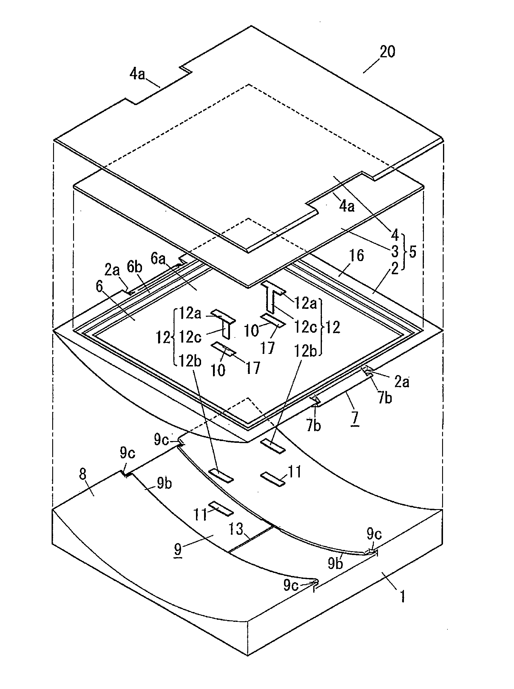
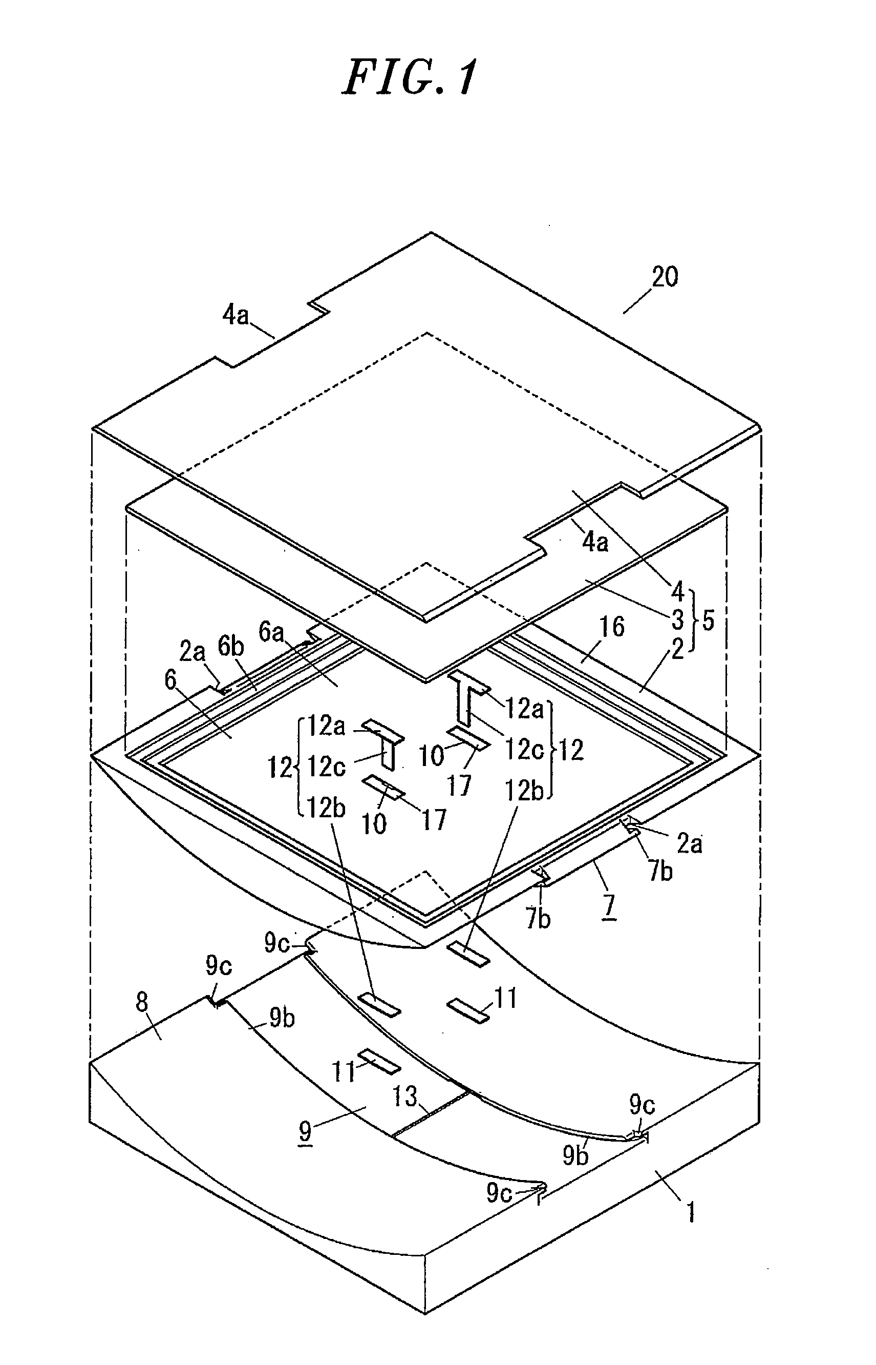
[0026]An illumination device according to a first embodiment will now be described with reference to FIGS. 1 through 10 which form a part hereof.

[0027]The illumination device 20 of the present embodiment includes a light emitting panel 5 having an electroluminescence element 3, and a box-shaped device body 1 to which the light emitting panel 5 can be detachably attached. While an organic electroluminescence element is used as the electroluminescence element 3 in the illumination device 20 of the present embodiment, the present invention is not limited thereto. An inorganic electroluminescence element may be used as the electroluminescence element 3. While the color of the light emitted by the electroluminescence element 3 is white in the illumination device 20 of the present embodiment, the present invention is not limited thereto.

[0028]The electroluminescence element 3 is formed to have a rectangular perimeter.

[0029]The electroluminescence element 3 includes a plate-like circuit bo...

Example

Second Embodiment

[0064]An illumination device 20 according to a second embodiment will now be described with reference to FIGS. 11A and 11B.

[0065]The basic configuration of the illumination device 20 of the second embodiment remains the same as that of the first embodiment. The second embodiment differs from the first embodiment in that the attachment portion 7 is provided in the device body 1 and the groove portion 9 is provided in the light emitting panel 5. The same components as those of the first embodiment will be designated by like reference symbols with no description made thereon.

[0066]In the illumination device 20 of the present embodiment, the attachment portion 7 is provided on the surface 8 of the device body 1. Briefly, in the illumination device 20 of the present embodiment, the attachment portion 7 for attaching / detaching the light emitting panel 5 to / from the device body 1 to slide along the first curved surface or the second curved surface is provided on the surfac...


PUM


Abstract

An illumination device includes a light emitting panel and a device body to which the light emitting panel is detachably attached. The light emitting panel has a rear surface serving as a first curved surface. The device body has a surface serving as a second curved surface conforming to the first curved surface. An attachment portion for attaching/detaching the light emitting panel to/from the device body to slide along the first curved surface or the second curved surface is provided on one of the rear surface of the light emitting panel facing the device body and surface of the device body facing the light emitting panel. A groove portion for enabling the attachment portion to slide is provided on the other of the rear surface of the light emitting panel facing the device body and the surface of the device body facing the light emitting panel.

Description

FIELD OF THE INVENTION[0001]The present invention relates to an illumination device.BACKGROUND OF THE INVENTION[0002]Conventionally, there is proposed a light-emitting-panel-type illumination device arranged on a ceiling (see, e.g., Japanese Patent Application Publication No. 2007-250302). As shown in FIG. 12, the light-emitting-panel-type illumination device includes a flat light emitting panel 61 for radiating light downward from the front surface 61a thereof, a housing 63 for accommodating the light emitting panel 61 by covering the rear surface 61b of the light emitting panel 61 and a holder member 62 arranged within the housing 63 to hold the light emitting panel 61.[0003]The light emitting panel 61 includes a substrate (not shown), an organic EL layer (not shown) having a first electrode layer, an organic light emitting layer and a second electrode layer formed one above another on the substrate, a first seal member (not shown) and a second seal member (not shown). The first s...

Claims


Application Information

Patent Timeline
IPC IPC(8): F21V21/00
CPCF21Y2105/006F21V21/34F21Y2105/00F21Y2115/20
Inventor HIRANO, AKIHIROMIYAKAWA, NOBORUKOTERA, RYUSUKEFUKANO, SATOSHITAKEDA, MASASHI
Owner PANASONIC INTELLECTUAL PROPERTY MANAGEMENT CO LTD
Why Eureka
Try Eureka