
Bariatric seating furniture

Active Publication Date: 2009-12-03
KRUEGER INT
View PDF9 Cites 0 Cited by
  • Summary
  • Abstract
  • Description
  • Claims
  • Application Information

AI Technical Summary

Benefits of technology

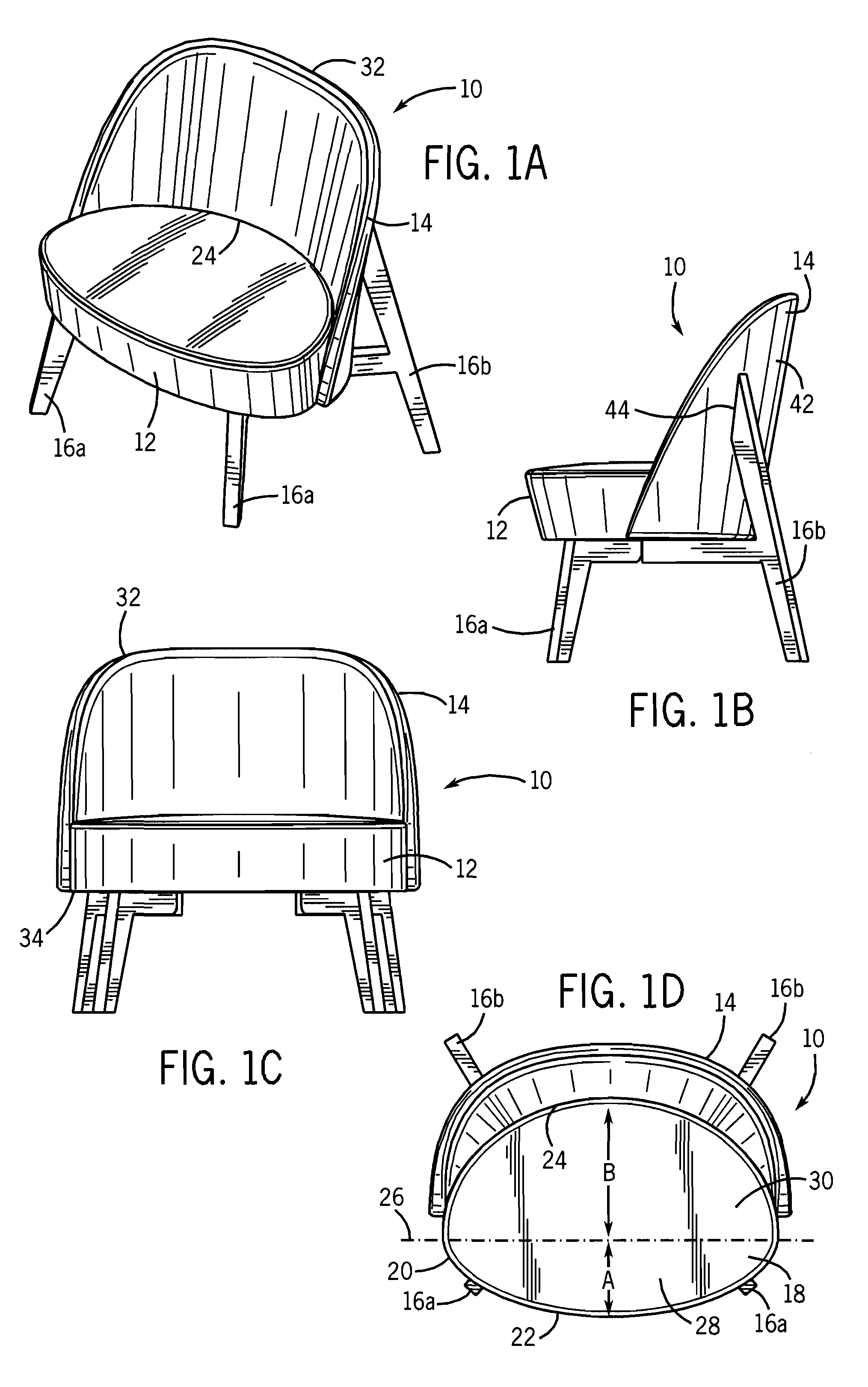
[0012]The seat portion is configured such that the maximum depth of the front seating area is less than the maximum depth of the rear seating area to enhance the ease of ingress and egress for a bariatric patient. Preferably, both the front perimeter edge and the rear perimeter edge are generally semi-elliptical.
[0013]The seating furniture includes a back portion that extends along the rear perimeter edge defining the rear seating area. Configuration of the back portion aids in supporting a patient during the ingress and egress from the seating furniture.
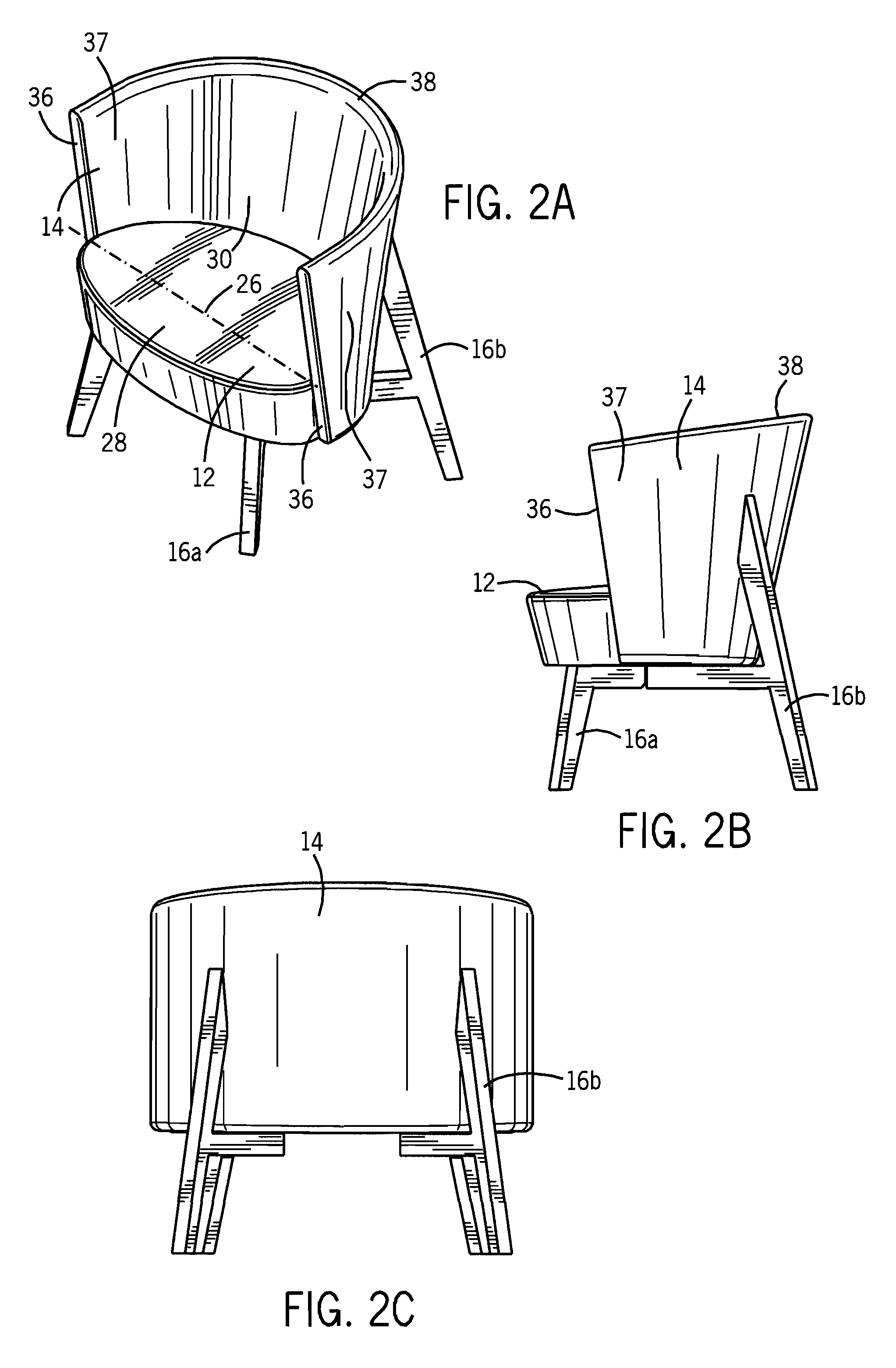
[0014]The seating furniture further includes at least two pair of legs for supporting the seating furniture on a horizontal support surface. Preferably, both the front legs and the rear legs extend outwardly past the outer perimeter that defines the seat portion to provide enhanced stability for the seating furniture. In one embodiment, the rear legs of the seating furniture are joined the back portion at a location above the seat portion to provide enhanced support for the back portion.

Problems solved by technology

It is notable that when an obese person sits in the traditional orientation in a standard sized chair, with hips parallel to the chair back, poor posture is often observed due to the seat's inability to properly accommodate the person's body size.
This furniture has the awkward appearance of being for an obese person such that the patient is required to use a “special” chair.
This approach is in conflict with health care providers' ultimate goal of treating all patients with respect and dignity, and presents bariatric patients with additional barriers and stigma in the common areas and examination / treatment rooms of health care facilities.
In addition, the stretched and reinforced versions typically fail to comfortably seat the remainder of the patient population, so that the health care provider who seeks to make both obese and non-obese patients comfortable, including most hospitals, doctor's offices, therapy providers and the like, are obliged to have both bariatric and non-bariatric seating available.
Current bariatric seating solutions also fail to appreciate the fact that obese people frequently are unable to rest their arms directly against their bodies due to a combination of arm and body girth.
In addition, obese people often sit higher in chairs due to additional tissue covering the rear end and thighs.
Further, chairs that have openings at the side and / or back fail to provide a sense of visual privacy, and again such furniture falls short of health care providers' desire to provide an environment that allows all patients to be as physically and emotionally comfortable as possible.
It does not make accommodations for a bariatric patient's need to shift a large body weight, usually heavily balanced toward the rear of the person, forward and out of a seated position.
In addition, the angle of approach and departure from a seating solution is significant.

Method used


Image

  • Bariatric seating furniture
  • Bariatric seating furniture
  • Bariatric seating furniture

Examples


first embodiment

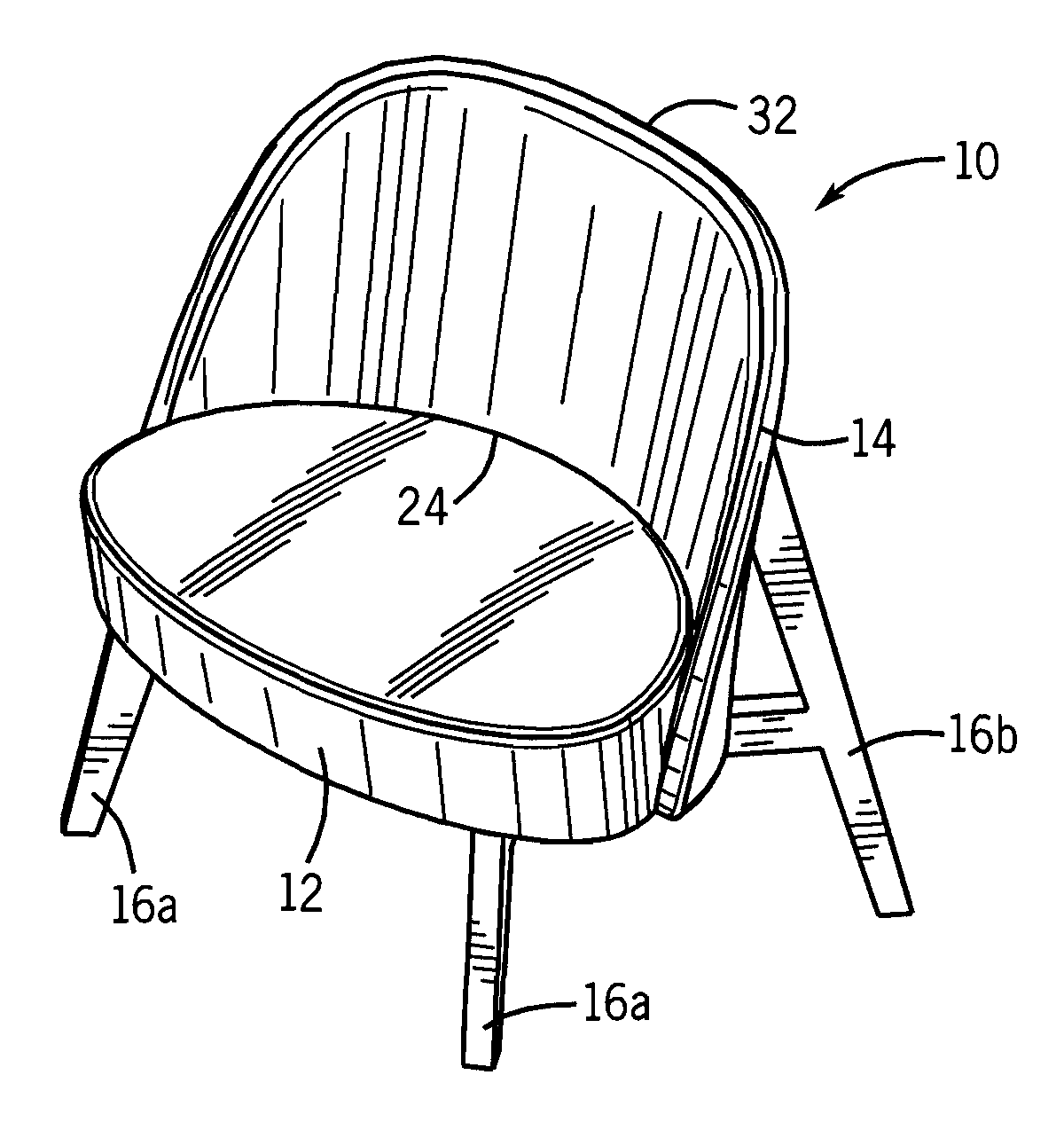
[0027]Referring first to FIGS. 1A-1D, there shown is the seating furniture 10 constructed in accordance with the present disclosure. In the embodiment shown in FIGS. 1A-1D, the seating furniture has the form of a chair designed to support a single occupant. The seating furniture 10 generally includes a seat portion 12, a back portion 14 and four legs 16. The legs 16 include a pair of front legs 16A and a pair of rear legs 16B that are designed to support the seat portion 12 above a generally horizontal support surface, such as the floor.

[0028]Referring to FIG. 1D, the seat portion 12 includes a top support surface 18 that is generally defined by an outer perimeter 20. In accordance with the present disclosure, the outer perimeter 20 includes a front perimeter edge 22 and a rear perimeter edge 24. In the embodiment illustrated, both the front perimeter edge 22 and the rear perimeter edge 24 have the general shape of a semi-ellipse. In the embodiment illustrated, the front perimeter e...

embodiment 70

[0046]Referring now to FIG. 9, there shown is a multi-seat embodiment 70 of the seating furniture. In the multi-seat embodiment, three separate seating areas 72A, 72B and 72C are supported by a single pair of front legs 16A and rear legs 16B. Each of the seating areas 72A-72C includes a seat portion 12 and a back portion 14. The seat portion 12 and back portion 14 are constructed similar to the seat portion 12 and back portion 14 shown in the embodiment of FIGS. 4A-4D.

[0047]Referring now to FIG. 10, there shown is yet another alternate embodiment of the seating furniture 10. In the embodiment shown in FIG. 10, the seating furniture 10 includes a pair of seating elements 74A and 74B along with a table surface 76. Each of these seating elements 74A, 74B includes a seat portion 12 and a back portion 14 constructed in accordance with the embodiment shown in FIGS. 1A-1D. The seating furniture of FIG. 10 includes a pair of front legs 16A and rear legs 16B that are also each connected in a...


PUM


Abstract

An article of seating furniture that is particularly desirable for use with bariatric patients is disclosed. The seating furniture includes a seat portion that includes a front seating area and a rear seating area. The front seating area is defined by a generally semi-elliptical front perimeter surface while the rear seating area is defined by a different, generally semi-elliptical rear perimeter surface. The surface area of the front seating area is less than the surface area of the rear seating area to provide enhanced ingress and egress for a bariatric patient. The seating furniture includes a back portion and two pair of support legs that further enhance the desirability of the seating furniture for a bariatric patient.

Description

CROSS-REFERENCE TO RELATED APPLICATION[0001]The present application is based on and claims priority to U.S. Provisional Patent Application Ser. No. 61 / 058,435, filed on Jun. 3, 2008.BACKGROUND[0002]The trend toward obesity has impacted health care industries more than some others, since health care providers attempt to treat obesity as well as treating patients dealing with the side effects of obesity, including vascular difficulties, diabetes, and so forth.[0003]Health care providers and vendors to the health care industry have been required to develop products that will suit the unique needs of this population, including wheelchairs, toilets, and hospital beds that support additional size and weight. Furniture for waiting rooms and patient examination rooms are also needed.[0004]The Business and Institutional Furniture Manufacturing Association (BIFMA) promulgates preferred standards for such furniture. Typically, attempts to provide furniture for this population of patients focus...

Claims


Application Information

Patent Timeline
IPC IPC(8): A47C1/00
CPCA47C15/004
Inventor CRAMER, E. DANIELJAMES, PAUL A.
Owner KRUEGER INT
Learn More