Terminal device

Active Publication Date: 2015-09-17
PANASONIC INTELLECTUAL PROPERTY MANAGEMENT CO LTD
View PDF11 Cites 0 Cited by
  • Summary
  • Abstract
  • Description
  • Claims
  • Application Information

AI Technical Summary

Benefits of technology

[0014]The terminal device of the present disclosure is configured such that the terminal plate is not in rotation symmetry with respect to a rotation axis passing through the center of the screw hole. Th

Problems solved by technology

If the second leg portion is inserted into the attachment hole corresponding to the first leg portion (a first attachment hole) and if the first leg portion is inserted into the attachment hole corresponding to the second leg portion (a second attachment hole), there is a possibility that the lengt

Method used


Image

  • Terminal device
  • Terminal device
  • Terminal device

Examples


Example

[0023]An embodiment in which the technical concept of the present invention is applied to an operation terminal device of a remote monitoring control system disclosed in Japanese Unexamined Patent Application Publication No. 2001-86577 will now be described in detail. However, a terminal device to which the technical concept of the present invention can be applied is not limited to the operation terminal device of the present embodiment.

[0024]First, a remote monitoring control system which employs the operation terminal device according to the present embodiment will be briefly described with reference to FIG. 7.

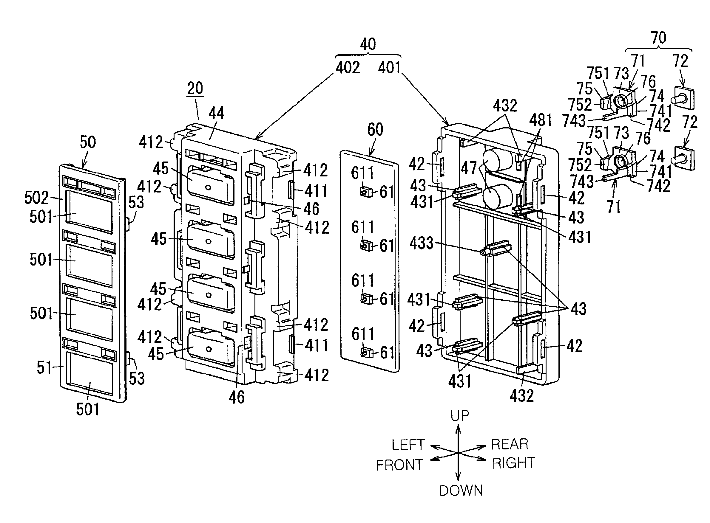
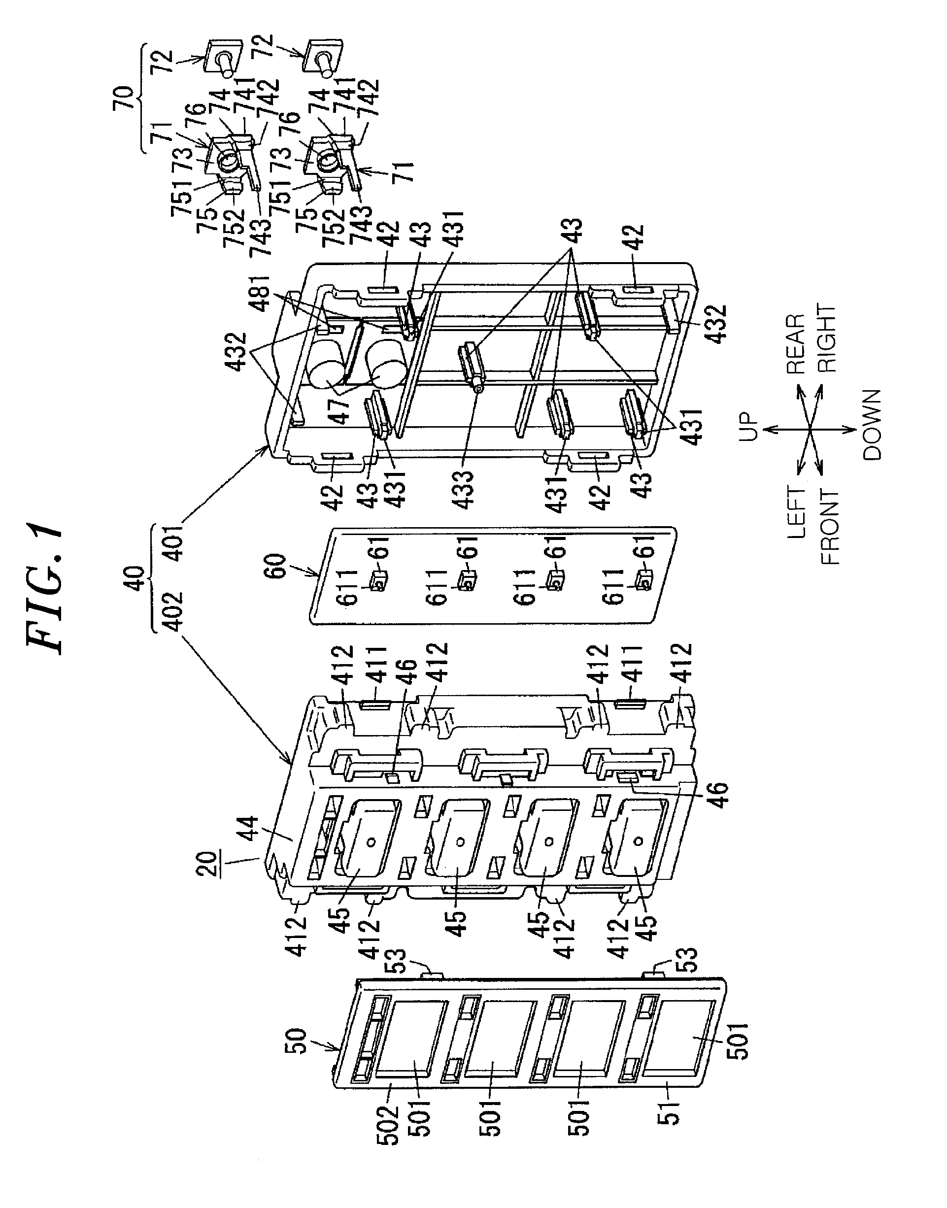
[0025]The remote monitoring control system includes a transmission processing device 81, an operation terminal device 20, and control terminal devices 82. The operation terminal device 20 for monitoring the operation states of switches 61 and the control terminal devices 82 for controlling loads 821 are connected to the transmission processing device 81 through two-wire-type...


PUM


Abstract

A terminal plate includes a main portion having a screw hole, and a first and second leg portion which protrude from the main portion in the same direction. The first leg portion is formed longer than the second leg portion. The device housing includes an outer wall which has a first attachment hole into which the first leg portion is inserted, a second attachment hole into which the second leg portion is inserted, and a depressed portion into which the terminal screw is inserted. The printed wiring board is electrically connected to the first leg portion, and a center of the screw hole of is misaligned with respect to a straight line extending through a center of the first attachment hole and a center of the second attachment hole when the terminal plate is attached to the device housing and seen in a direction perpendicular to the main portion.

Description

CROSS-REFERENCE TO RELATED APPLICATION[0001]This application claims priority to Japanese Patent Application No. 2014-047998 filed on Mar. 11, 2014, the entire contents of which are incorporated herein by reference.TECHNICAL FIELD[0002]The present disclosure relates to a terminal device.BACKGROUND ART[0003]Conventionally, there is provided a remote monitoring control system in which a transmission processing device, an operation terminal device and a control terminal device are connected by two signal lines (see, e.g., Japanese Unexamined Patent Application Publication No. 2001-86577). In the remote monitoring control system, specific addresses are respectively allotted to the operation terminal device and the control terminal device.[0004]The operation terminal device includes a plurality of switches. As the states of the switches are changed, e.g., by pressing the switches, the operation terminal device transmits the information as operation data to the transmission processing devi...

Claims


Application Information

Patent Timeline
IPC IPC(8): H05K5/00
CPCH05K5/0052H05K7/1469H01R4/34H01R9/2416
Inventor HARAGUCHI, TAKU
Owner PANASONIC INTELLECTUAL PROPERTY MANAGEMENT CO LTD
Why Eureka
Try Eureka