Fabric assembly suitable for resisting ballistic objects and method of manufacture

Inactive Publication Date: 2013-03-21
EI DU PONT DE NEMOURS & CO
View PDF3 Cites 6 Cited by
  • Summary
  • Abstract
  • Description
  • Claims
  • Application Information

AI Technical Summary

Benefits of technology

The present invention describes a fabric assembly that can withstand ballistic objects. The fabric assembly comprises two sections: a first section made of multiple layers of compacted fabric layers made from continuous yarn with high tenacity and modulus, and a second section made of separate layers that are not secured together by parallel connector lines. The connectors in the first section have a force to break in tension of not greater than 65 N and are concentrated along a series of parallel lines on both outer surfaces of the fabric. The second section has unconnected fabric layers that remain between the connector lines. The fabric assembly has a high level of protection against ballistic objects. A method for manufacturing the fabric assembly is also provided.

Problems solved by technology

However, reduction in apparel weight should not be achieved at the expense of a significant reduction in anti-ballistic performance.

Method used


Image

  • Fabric assembly suitable for resisting ballistic objects and method of manufacture
  • Fabric assembly suitable for resisting ballistic objects and method of manufacture
  • Fabric assembly suitable for resisting ballistic objects and method of manufacture

Examples


examples

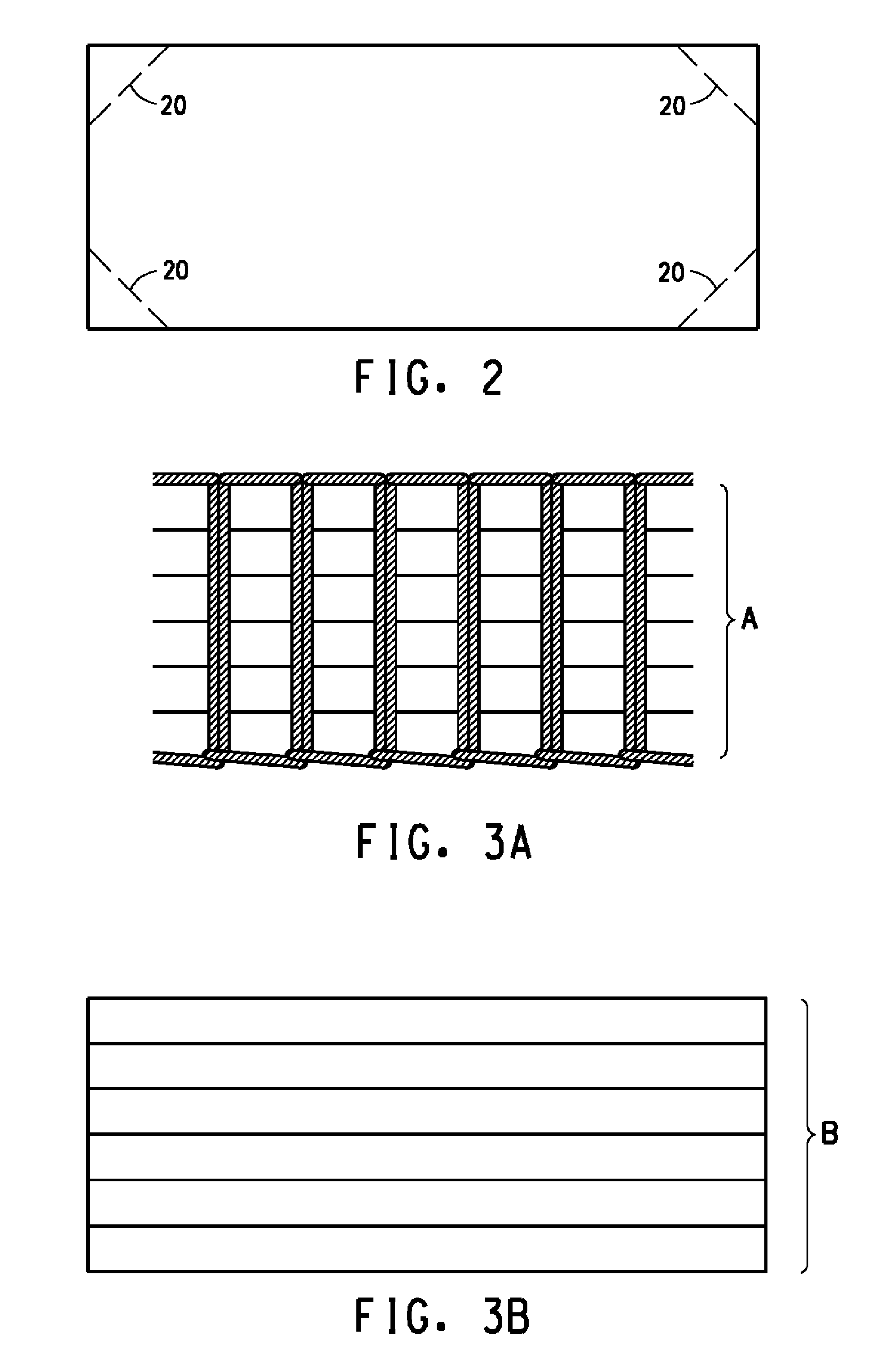
[0088]The example constructions described herein are comprised of sub-assemblies of first (connected) sections and / or second (unconnected) sections of anti-ballistic fabric plies. Descriptions of all the anti-ballistic fabrics used to generate the examples are provided in Table 1. A description of the consolidated sub-assemblies is provided in Table 2

[0089]Examples prepared according to the process or processes of the current invention are indicated by numerical values. Control or Comparative examples are indicated by letters. Data and test results relating to the Comparative and Inventive Examples are shown in Table 3

Description of Fabric Layers

[0090]Layers of the following high tenacity fiber fabrics used to fabricate sub-assemblies with connectors or incorporated as unconnected ply sub-assemblies in the construction of the inventive and comparative examples are provided below and in Table 1.

[0091]Fabric layer “F3” was a plain weave woven fabric of 600 denier (667 dtex) poly(p-phe...

example 13

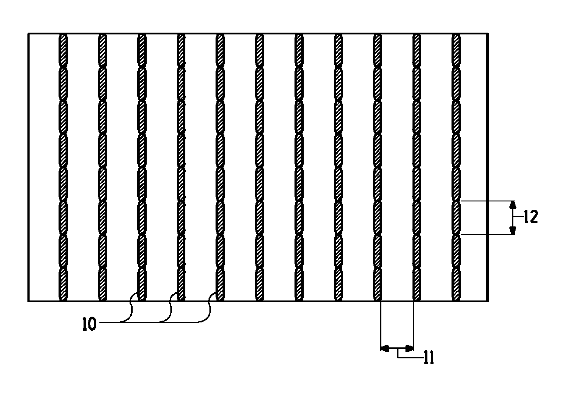
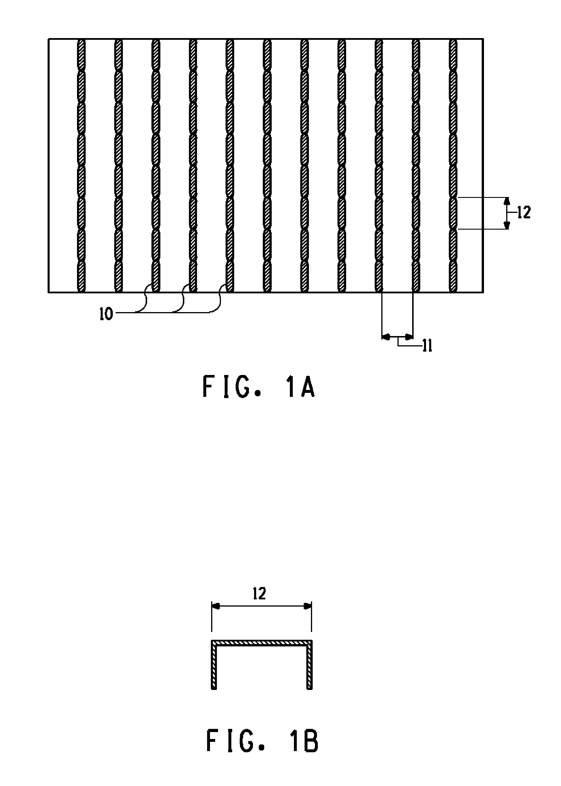
[0103]In this example, one first section sub-assembly (designated C1 in Table 2) containing fifteen layers of fabric F3 having length and width dimensions of 38 cm×38 cm (15″×15″) were held together by connector threads sewn through, and orthogonal to, the plane of the fifteen layers so as to form a first section. The sewn through series of connectors were concentrated along a series of parallel connector lines as viewed from either outer surface. The parallel connector lines were generated with continuous threads using a lock stitch. The connector material was 351 dtex (316 denier) Kevlar® thread from United Thread Mills having a force to break of 29N. The connector pitch length was 3.18 mm, and the connector row spacing was 6.35 mm. The first section sub-assembly with connectors was then combined with a second section comprising sixteen loose unconnected layers of fabric F3 cut to 38 mm×38 mm (15″×15″) by corner stitching into an article with an areal density of 4.64 kg / m2. The co...

example 14

[0105]In this example, one first section sub-assembly (designated C3 in Table 4) containing fifteen layers of fabric F3 having length and width dimensions of 38 cm×38 cm (15″×15″) were held together by connector threads sewn through, and orthogonal to, the plane of the fifteen layers so as to form a first section. The sewn through series of connectors were concentrated along a series of parallel connector lines as viewed from either outer surface. The parallel connector lines were generated with continuous thread using a lock stitch. The connector material was 351 dtex (316 denier) Kevlar® thread from United Thread Mills having a force to break of 29N. The connector pitch length was 3.18 mm, and the connector row spacing was 12.7 mm. The first section sub-assembly with connectors was then combined with a second section comprising sixteen loose unconnected layers of fabric F3 cut to 38 mm×38 mm (15″×15″) by corner stitching into an article with an areal density of 4.62 kg / m2. The cor...


PUM

PropertyMeasurementUnit
Lengthaaaaaaaaaa
Lengthaaaaaaaaaa
Lengthaaaaaaaaaa

Abstract

A fabric assembly particularly useful as soft body armor has two or more separate sections each containing a number of fabrics made from yarns having a tenacity of at least 7.3 grams per dtex and a modulus of at least 100 grams per dtex. At least one of the sections in the fabric assembly is comprised of compressed fabrics attached by connector yarns having a force to break in tension not greater than 65N concentrated along a series of parallel connector lines as viewed from the fabric on both outer surfaces of the first section, the connector lines being spaced from 1.8 mm to 51 mm apart defining regions between the connector lines where the fabric layers remain unconnected.

Description

RELATED APPLICATION [0001]The present patent application is a continuation-in-part of Ser. No. 13 / 169,598 filed Jun. 27, 2011 which is a continuation-in-part of Ser. No. 12 / 369,227 filed Feb. 11, 2009 which in turn is a continuation-in-part of Ser. No. 12 / 368,539 filed Feb. 10, 2009, now abandoned.BACKGROUND OF INVENTION[0002]1. Field of the Invention[0003]This invention relates to a fabric assembly particularly suitable as ballistic resistant soft body armor and method of manufacture.[0004]2. Description of the Related Art[0005]Many designs for body armor for resisting ballistic threats have been proposed and many commercialized. Designs are made to increase comfort by the wearer and / or to add extra penetration resistance without increasing areal density. Comfort is generally increased by making the body armor lighter and more flexible to allow freedom of motion by the wearer. However, reduction in apparel weight should not be achieved at the expense of a significant reduction in a...

Claims


Application Information

Patent Timeline
IPC IPC(8): B32B5/06B32B37/00B32B7/14B32B5/02B32B7/08
CPCB32B5/06B32B5/02B32B7/08Y10T29/49833B32B37/0084F41H5/0485Y10T29/49947B32B7/14D03D1/0052D03D11/00Y10T428/249921
Inventor CARBAJAL, LEOPOLDO ALEJANDROEGRES, JR., RONALD G.
Owner EI DU PONT DE NEMOURS & CO
Why Eureka
Try Eureka