System and method for real-time monitoring of power system

a power system and real-time monitoring technology, applied in the field of real-time monitoring systems of power systems, can solve the problems of time delays and excessive utilization of communication bandwidth

a power system and real-time monitoring technology, applied in the field of real-time monitoring systems of power systems, can solve the problems of time delays and excessive utilization of communication bandwidth

US20130073108A1Inactive Publication Date: 2013-03-21GENERAL ELECTRIC CO

Image

  • System and method for real-time monitoring of power system
  • System and method for real-time monitoring of power system
  • System and method for real-time monitoring of power system

Examples


Embodiment Construction

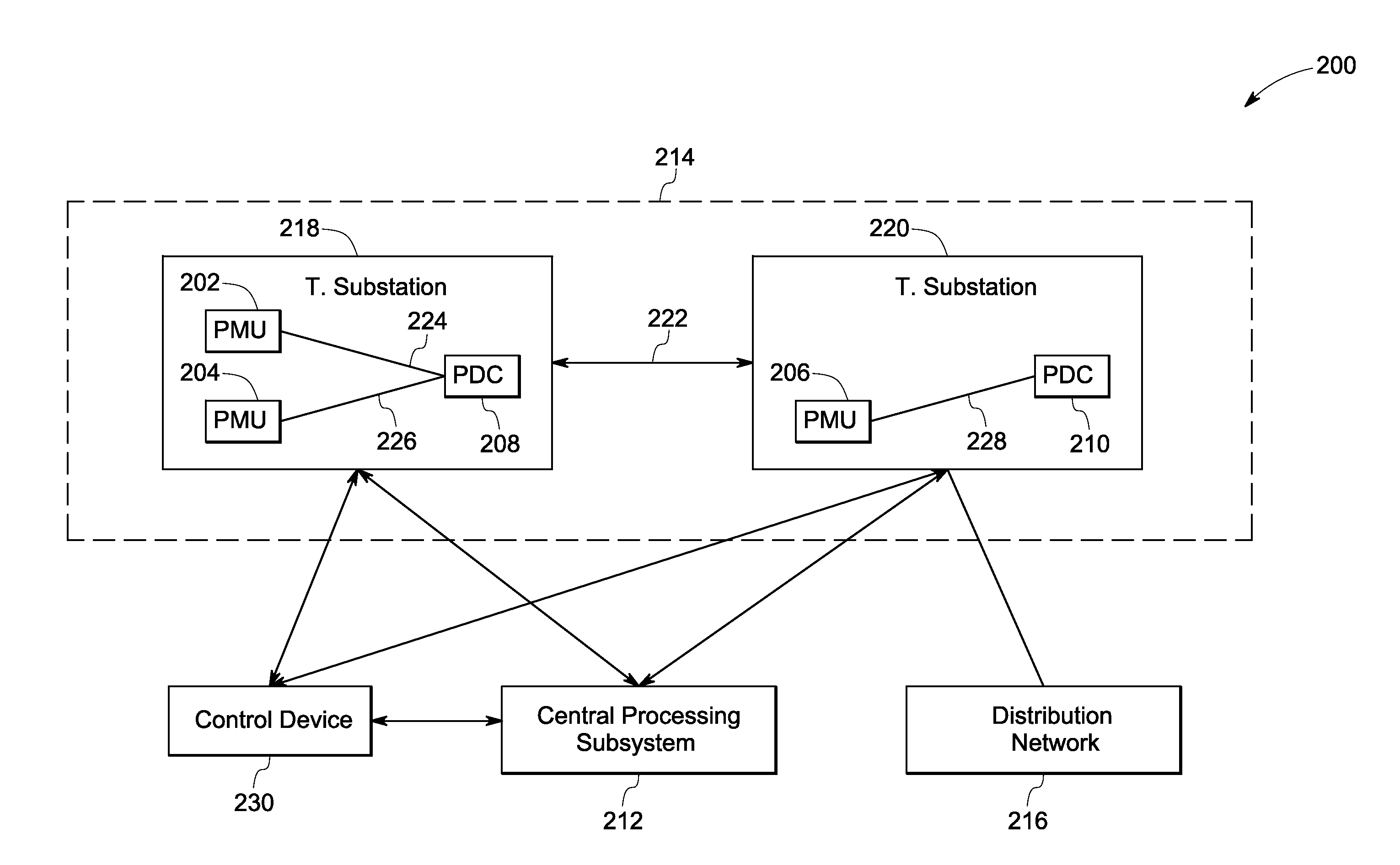
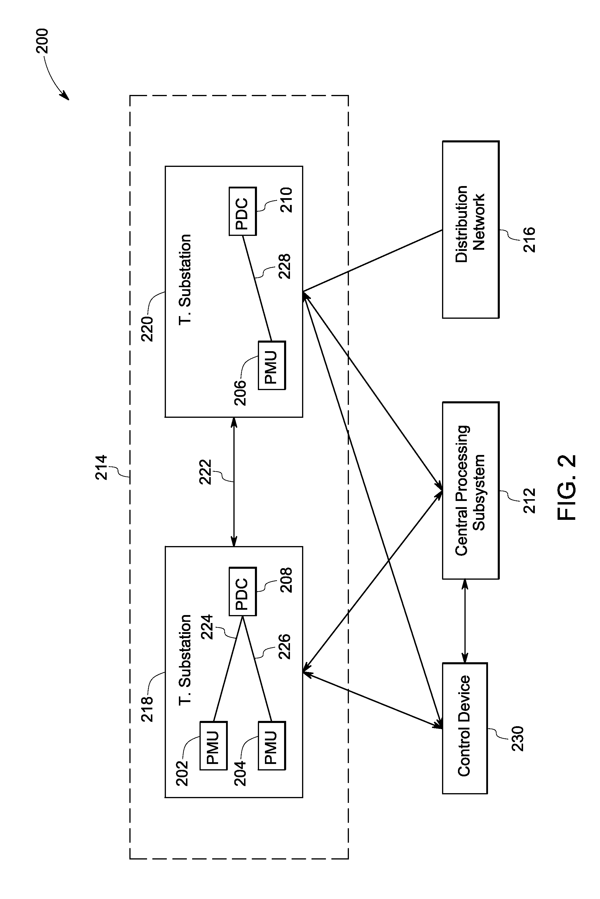
[0011]As discussed in detail below, embodiments of the present systems and techniques include a distributed wide area monitoring system that monitors and controls a power system in real time. The distributed wide area monitoring system includes a plurality of phasor measurements units (PMUs) and a plurality of processing subsystems. In one embodiment, the plurality of processing subsystems are phasor data concentrators. The PMUs measure synchronized phasor data at respective locations in the power system. The synchronized phasor data, for example, includes phasor currents and phasor voltages. The processing subsystems receive synchronized phasor data from at least one of the PMUs. Particularly, the processing subsystems receive the synchronized phasor data from at least one of the PMUs that is located in a local area network or a neighboring network of the receiving processing subsystems. The processing subsystems determine one or more respective system parameters by processing the ...


PUM


Abstract

A real-time distributed wide area monitoring system is presented. The real-time distributed wide area monitoring system includes a plurality of phasor measurement units that measure respective synchronized phasor data of voltages and currents. The real-time distributed wide area monitoring system further includes a plurality of processing subsystems distributed in a power system, wherein at least one of the plurality of processing subsystems is configured to receive a subset of the respective synchronized phasor data, process the received subset of the respective synchronized phasor data to determine respective system parameters, wherein the plurality of processing subsystems are time synchronized.

Description

BACKGROUND[0001]An electric power system typically includes a power transmission and / or power distribution network interconnecting geographically separated regions, and a plurality of power transmission and distribution substations. The substations include equipment for transforming voltages and for switching connections between individual lines of the power system. Power generation and load flow to consumers is managed by a central Energy Management System (EMS) and / or supervised by a Supervisory Control And Data Acquisition (SCADA) system. The electric power system may also include multiple phasor measurement units (PMUs). Typically these PMUs are distributed over a large geographic area, i.e. over tens to hundreds of kilometers. These PMUs generate synchronized phasor measurements or snapshots collected across the electric power system. The phasor measurements are time-stamped complex values (amplitude and phase) of local electric quantities, such as, currents, voltages and load ...

Claims


Application Information

Patent Timeline
21 Mar 2013
Publication
US20130073108A1
IPC
G06F1/28; G06F19/00; G01R21/06
CPC
G01R19/2513; Y02E60/728; Y04S10/265; Y02E60/00; Y04S10/00; Y04S10/22; Y02E40/70
Inventors
KOLWALKAR, AMOL RAJARAM