
Apparatus, method, and system for wide-area protection and control using power system data having a time component associated therewith

Active Publication Date: 2008-03-20
SCHWEITZER ENGINEERING LABORATORIES
View PDF44 Cites 122 Cited by
  • Summary
  • Abstract
  • Description
  • Claims
  • Application Information

AI Technical Summary

Benefits of technology

[0010]In yet another embodiment, provided is a method for providing protection, control and monitoring to an electric power system. The method generally includes the steps of acquiring remote power system signals at remote locations; calculating remote power system data from the acquired remote power system signals; associating the remote power system data with a time value to produce time-stamped remote power system data; transmitting the time-stamped remote power system data to a local location; receiving the time-stamped remote power system data at the local location; acquiring local power system signals; calculating local power system data from the sampled local power system signals; time-aligning the local power system data with the time-stamped remote power system data; and performing real-time automation, protection or control functions using the time-aligned local power system data and the time-stamped remote power system data.
[0011]In yet another aspect of the present invention, provided is an apparatus for providing protection, monitoring and control for an electric power system. The apparatus generally comprises an acquisition circuit for obtaining local analog signals from an electric power system; a sampling circuit for sampling the local analog signals; a communication channel for transmitting messages containing local power system data calculated from the local analog signals to a remote d

Problems solved by technology

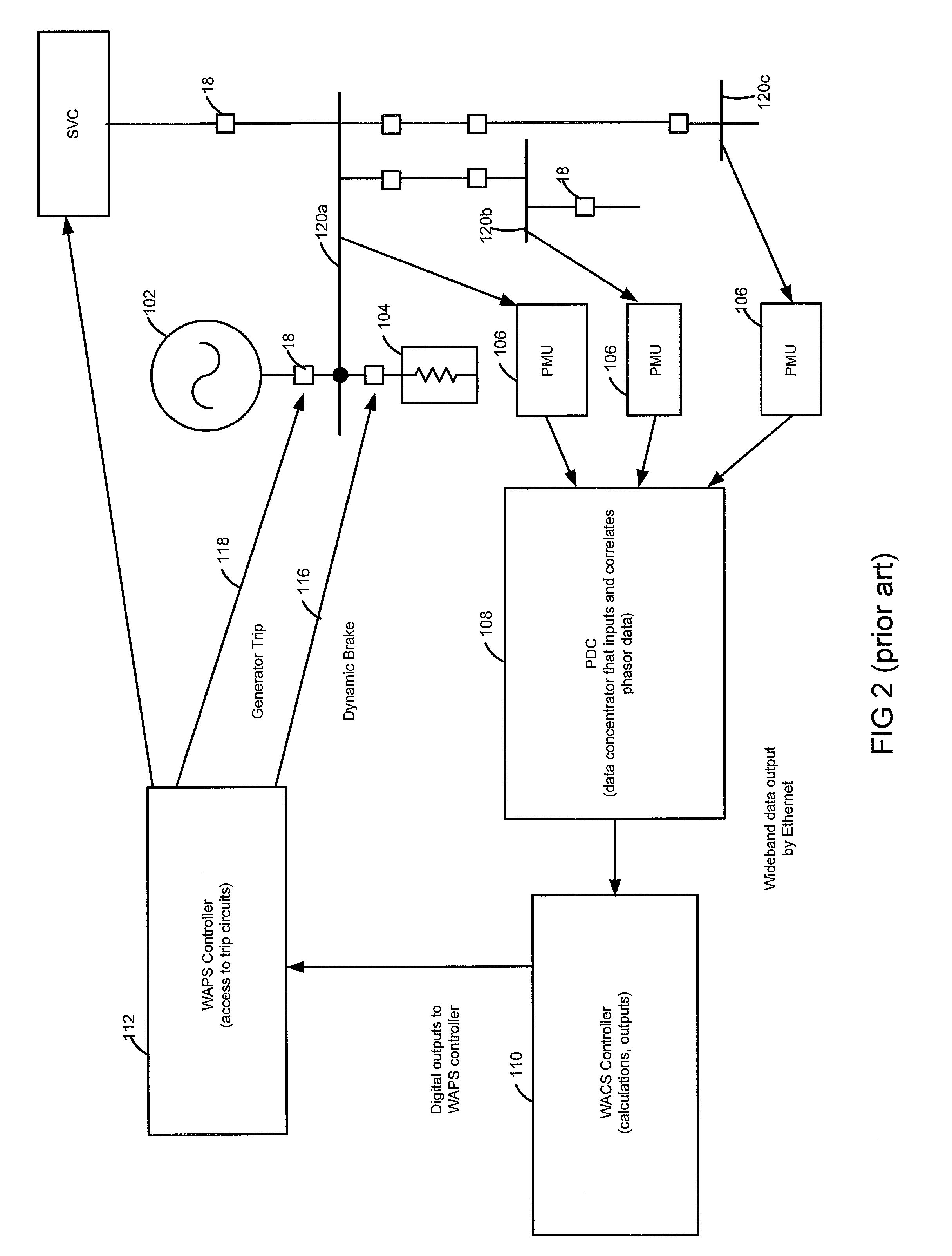
The result is that many of these existing systems require about 700 milliseconds before a control or protection command is issued.

Method used


Image

  • Apparatus, method, and system for wide-area protection and control using power system data having a time component associated therewith
  • Apparatus, method, and system for wide-area protection and control using power system data having a time component associated therewith
  • Apparatus, method, and system for wide-area protection and control using power system data having a time component associated therewith

Examples


Embodiment Construction

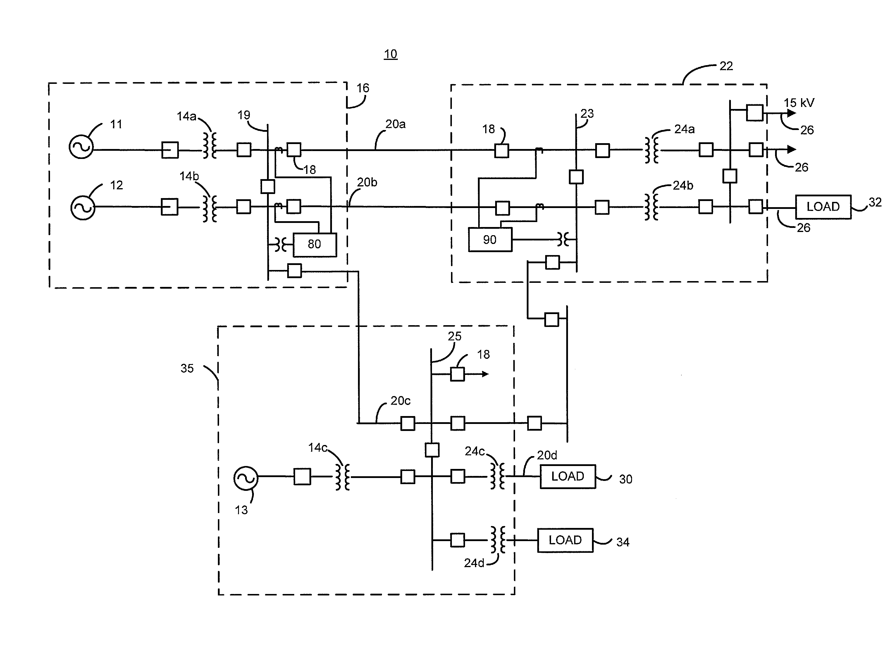
[0028]The present invention provides a method, apparatus, and system for power system protection, control and monitoring of an electrical power transmission or distribution system by comparing power system data having a time component associated therewith from disparate points on the electrical power transmission or distribution system. As will be described in more detail herein, a benefit of the present invention is that the comparison of the power system data takes place at or near to the real-time collection of the data. The system, apparatus, and method of the present invention also require fewer IEDs and CPUs for adequate processing and comparison of the data associated with power system information.

[0029]Throughout, the term “IED” or “intelligent electronic device” is to include, but not be limited to, any intelligent electronic device, such as, for example, a central processing unit (CPU), relay, phase measurement unit (PMU), phase measurement and control unit (PMCU), phasor ...


PUM


Abstract

An apparatus, system and method in an electrical system using power system information or data associated therewith having a time component associated therewith sampled or obtained from the electrical system at a local and a remote location, wherein the local and remote data are time aligned and used to provide control, monitoring, metering, and / or automation to the electrical system. The local IED may be adapted to receive power system data from the remote IED, time align the local and remote synchronized power system data, and perform math operations on the local and remote power system data.

Description

CROSS-REFERENCE TO RELATED APPLICATIONS[0001]This application claims benefit under 35 U.S.C. § 119(e) of U.S. Provisional Application Ser. No. 60 / 845,744, entitled “An Apparatus, Method, and System for Wide-Area Protection and Control Using Synchronized Phasors,” filed Sep. 19, 2007, naming Gregary C. Zweigle, Armando Guzman-Casillas, Ping Jiang and Charles E. Petras as inventors, the complete disclosure thereof being incorporated herein by reference.FIELD OF THE INVENTION[0002]This invention relates generally to apparatuses, methods, and systems for protection and control using power system data having a time component associated therewith. More specifically, this invention relates to apparatuses, methods, and systems for communicating power system data having a time component associated therewith between intelligent electronic devices for providing real-time automation, protection and control to electric power systems.BACKGROUND OF THE INVENTION[0003]System-wide protection, contro...

Claims


Application Information

Patent Timeline
IPC IPC(8): G01R21/00G01R21/06G06F19/00
CPCG01R19/2513H02H1/0061Y04S10/265Y02E60/728H02H7/261Y02E40/70Y02E60/00Y04S10/00Y04S10/22
Inventor ZWEIGLE, GREGARY C.GUZMAN-CASILLAS, ARMANDOPETRAS, CHARLES E.JIANG, PING
Owner SCHWEITZER ENGINEERING LABORATORIES
Learn More