Methods and systems for locating subjects and providing event notification within a tracking environment and badge for use therein

a tracking environment and event notification technology, applied in the field of methods and systems for locating subjects and providing event notification within the tracking environment and badges for use therein, can solve the problem of increasing installation costs

Inactive Publication Date: 2005-01-04
VERSUS TECHNOLOGY INC
View PDF36 Cites 107 Cited by
  • Summary
  • Abstract
  • Description
  • Claims
  • Application Information

AI Technical Summary

Benefits of technology

An object of the present invention is to provide improved methods and systems for locating subjects and providing event notification within a tracking environment and badge for use therein.
Still further in carrying out the above object and other objects of the present invention, a badge capable of transmitting substantially line-of-sight signals including a unique badge ID and substantially non-line-of-sight signals also including the unique badge ID is provided. The badge includes a first transmitter for transmitting a plurality of substantially non-line-of-sight signals including a longer interval, higher power, wide area, substantially non-line-of-sight signal and a shorter interval, lower power, local area, substantially non-line-of-sight signal. The badge further includes a second transmitter for transmitting a plurality of substantially line-of-sight signals.

Problems solved by technology

Such problems include the changing from a low frequency IR carrier to a high frequency IR carrier.
There are a number of drawbacks in using IR signals including: (1) if a badge is covered, its IR signal is blocked; and (2) an IR receiver must be placed in every room, thereby increasing installation cost.

Method used


Image

  • Methods and systems for locating subjects and providing event notification within a tracking environment and badge for use therein
  • Methods and systems for locating subjects and providing event notification within a tracking environment and badge for use therein
  • Methods and systems for locating subjects and providing event notification within a tracking environment and badge for use therein

Examples


Embodiment Construction

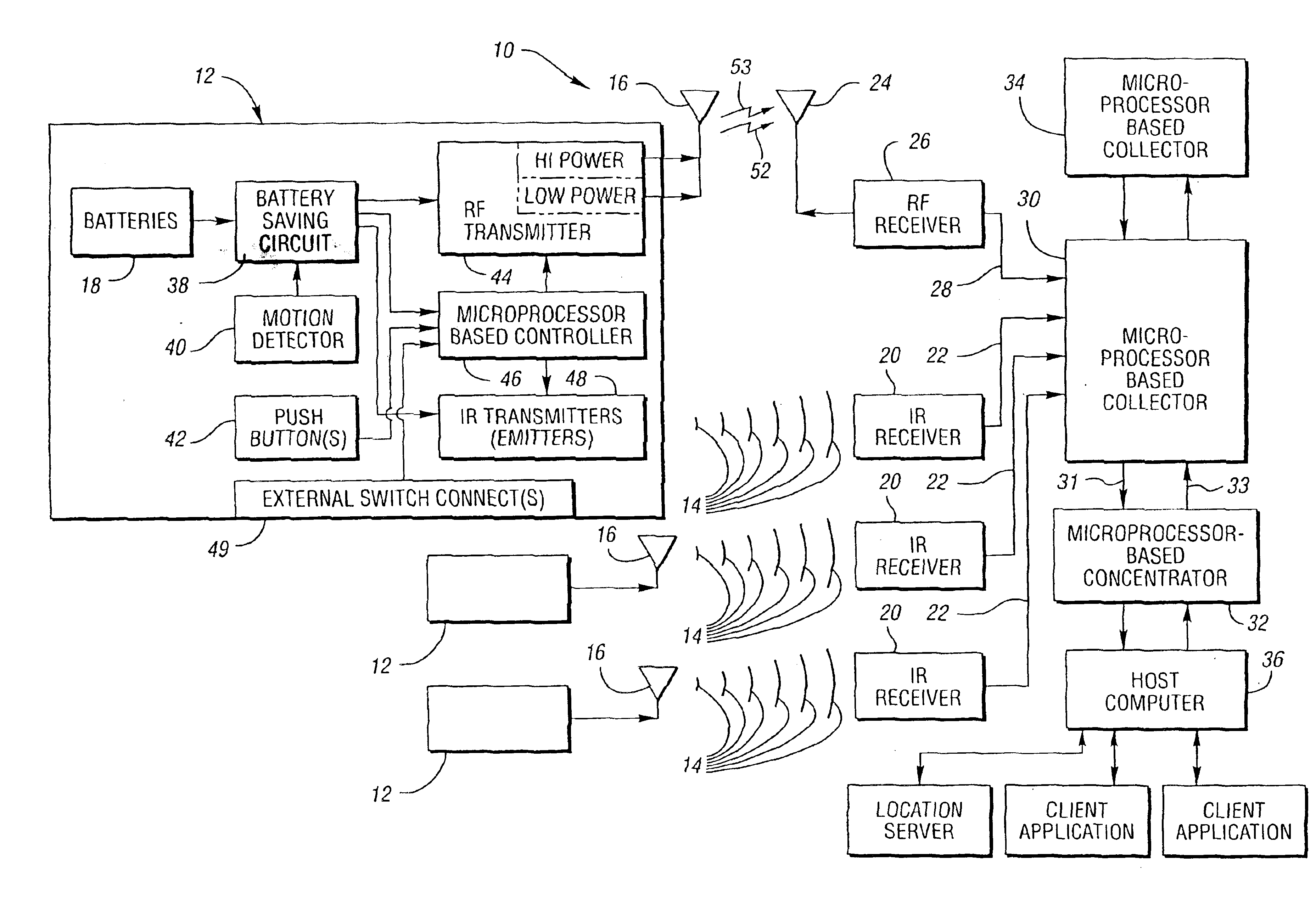
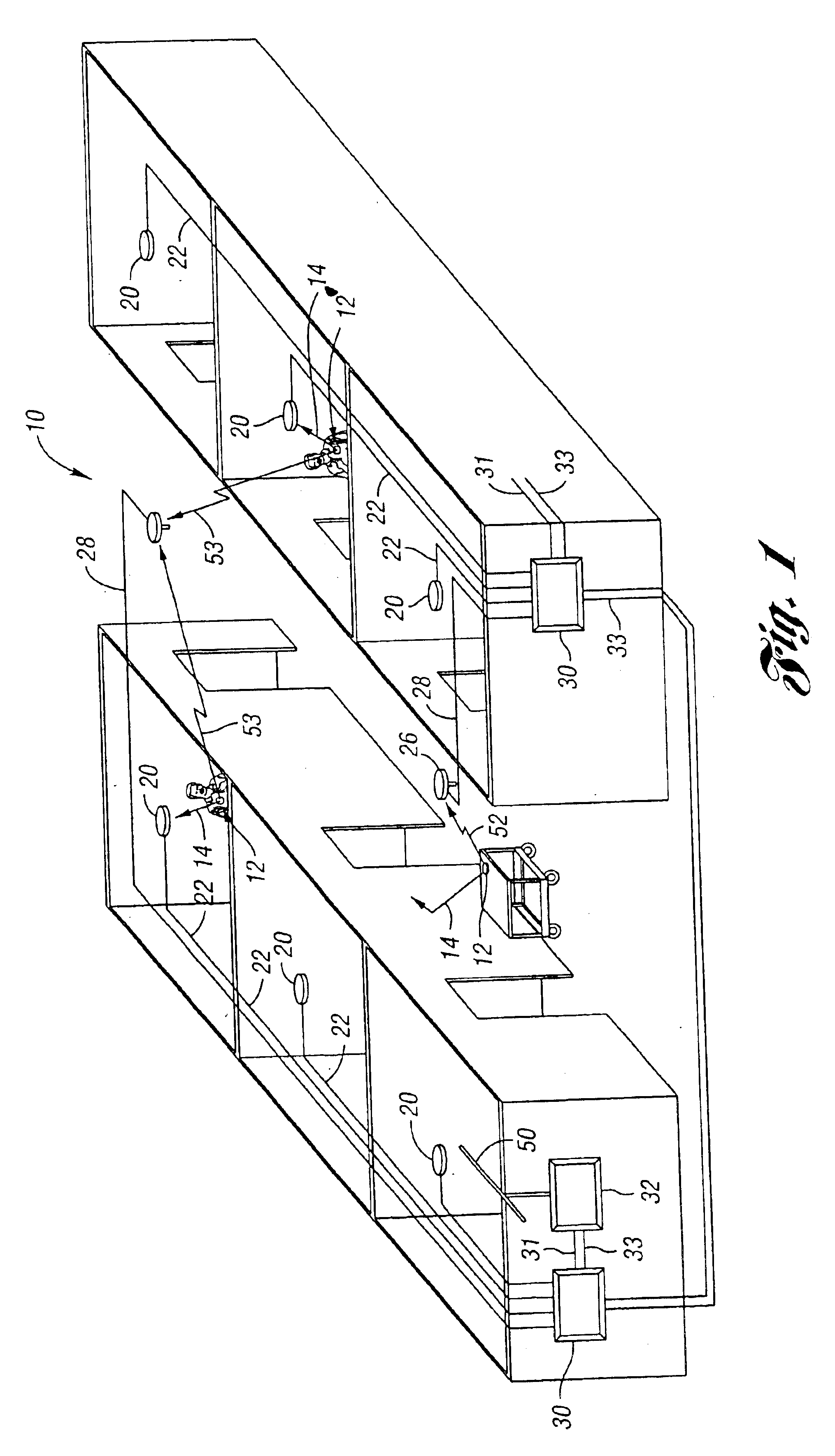
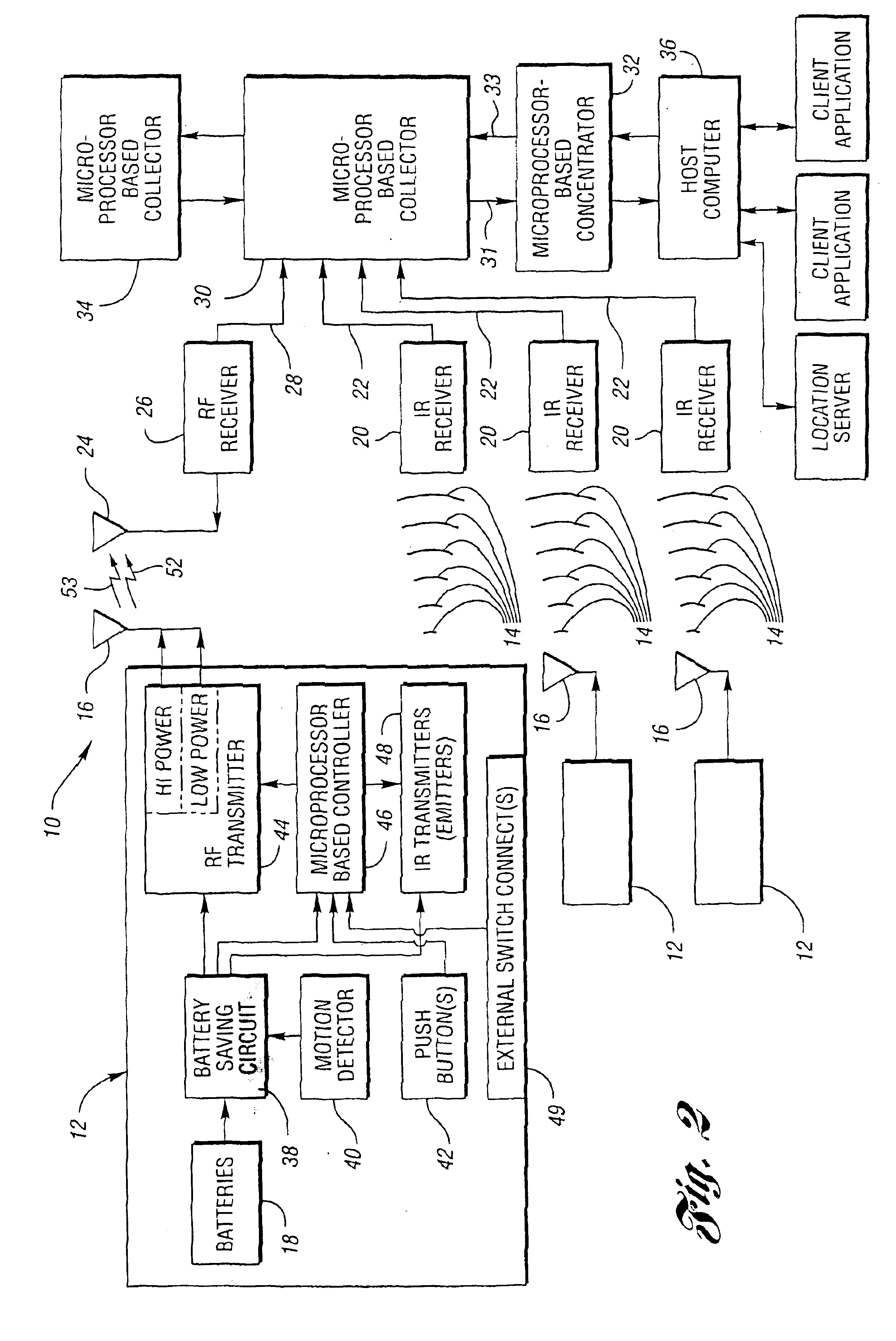
Referring now to FIGS. 1 and 2, there is illustrated a system, generally indicated at 10, for locating subjects (i.e. persons and objects) in a tracking environment. In general, the system is a combined infrared and radio frequency locating system which is adapted for use not only in medical applications, but also in non-medical applications. The system 10 is a fully automatic data collection system which provides real-time location information of personnel or equipment (i.e. subjects). Typically, information is collected using an in-ceiling and / or in-wall receiver network connected with common telephone-type wire to make accurate decisions and execute the appropriate responses. Typically, the components of the system 10 are relatively simple and modular.

In general, the system 10 includes a plurality of badges, each of which is generally indicated at 12. Each badge 12 is provided for each subject to be tracked within the tracking environment. In general, each badge emits one or more...


PUM


Abstract

A method, system and a badge utilized therein utilize both the radio frequency (RF) and infrared (IR) parts of the electromagnetic spectrum to locate subjects (i.e. objects and persons) within a tracking environment. The system includes a battery-operated, microprocessor-based badge for each subject to be located. Each badge automatically transmits: (1) shorter interval, digitized, infrared light signals to identify a delimited area zone of its subject's location; (2) shorter interval, digitized, lower power RF signals to provide a local area zone of its subject's location; and (3) longer interval, digitized, higher power RF signals to provide a wide area zone of its subject's location. Each badge transmits uniquely identifiable IR and higher power RF signals upon actuation of one or more push button switches integrated on the badge or a change of state of one or more external switch connections. Each higher power, longer interval, RF signal is a “supervisory” pulse. This pulse informs a host computer that the badge is in range of an RF receiver and is functional.

Description

BACKGROUND OF THE INVENTION1. Field of the InventionThis invention relates to methods and systems for locating subjects and providing event notification within a tracking environment and badges for use therein. In particular, methods and systems are provided for locating subjects within a tracking environment and providing each subject a mechanism to generate notification of varying events to the system in the environment wherein the system includes a badge for each subject to be located. Preferably, each badge is outfitted with one or more push button switches and / or one or more external switch connections.2. Background ArtAn identification system exists whereby a single microprocessor can simultaneously receive sensory input with its subcarrier removed and demodulate the data content on each sensory input. In turn, each sensory input can come from any number of different subcarriers. Such subcarriers include a 40 kHz infrared on / off shift key, and a 447.5 kHz infrared on / off shift...

Claims


Application Information

Patent Timeline
Patent Type & Authority Patents(United States)
IPC IPC(8): G07C9/00G01S19/48
CPCG01S5/16G06F19/327G06K19/0716G06K19/0728G06K19/07749G01S5/0226G06Q10/08G06Q50/22G06Q50/28G07C9/00103G07C9/00111G06Q10/06G16H40/20G16H40/67G07C9/27G07C9/28
Inventor TENARVITZ, HENRY J.
Owner VERSUS TECHNOLOGY INC
Why Eureka
Try Eureka