Method and a device for separating particles of a determined synthetic material from particles of different synthetic materials

a technology of synthetic materials and separating devices, which is applied in the direction of electrostatic separation, solid separation, chemistry apparatus and processes, etc., can solve the problems of insufficient homogeneity of reciprocal dragging between particles, inability to separate two different materials from one another, and a certain number of prior art problems, so as to achieve the effect of maximising the electrical field

Active Publication Date: 2013-03-28
CASSANI STEFANO
View PDF10 Cites 0 Cited by
  • Summary
  • Abstract
  • Description
  • Claims
  • Application Information

AI Technical Summary

Benefits of technology

[0045]As the electrical field reduces as the reciprocal distance between the armatures grows, in order to maximise the level of the electrical field and with it the deviating force acting on the particles, a preferable solution is to arrange pairs of armatures in series on the trajectory of the particles, which armatures face one another and are characterised by progressively growing differences of potential.

Problems solved by technology

The prior art suffers from a certain number of drawbacks, among which of not least importance is the fact that generally the reciprocal dragging between particles is not sufficient nor sufficiently homogeneous to give the particles an advantageous quantity of charge.
As the force to which the particles are to be subjected when they cross the electrical field depends on the density of the load, which in turn depends on the mass of particles subjected to rubbing, sometimes it is not possible to separate the two different materials from one another which charge up with the same polarity and are present in such proportions as to absorb the same charge density.

Method used


Image

  • Method and a device for separating particles of a determined synthetic material from particles of different synthetic materials
  • Method and a device for separating particles of a determined synthetic material from particles of different synthetic materials
  • Method and a device for separating particles of a determined synthetic material from particles of different synthetic materials

Examples


example 1

Relating to the Device of FIG. 8

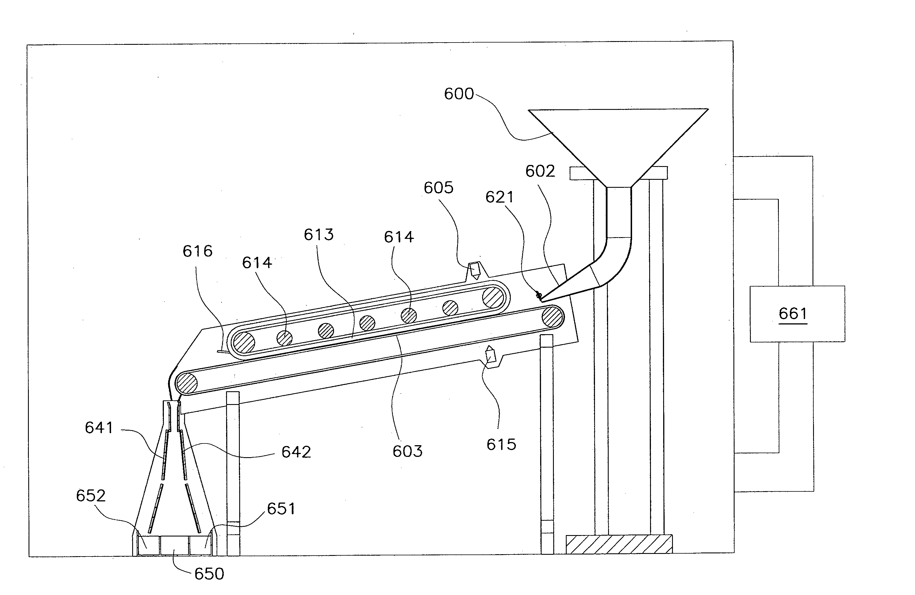
[0137]A granular mass is placed in the hopper 500, comprising granules in unknown proportions, singly constituted by one of the following materials: PMMA, PTFE, PET, PVC.

[0138]With the mass of PVC granules to be separated, the rubbing surface constituted by the base 503 of the chute is realised or clad with PVC.

[0139]The PVC granules do not therefore acquire any electrical charge by rubbing against the chute.

[0140]Three piles are obtained downstream of the electrical field, respectively a central pile 550 into which only the PVC granules fall, a pile 55 underlying the negative pole, into which the PMMA and PET granules fall, and a pile 552 underlying the positive pole into which the PTFE granules fall.

example 2

Relating to the Device of FIGS. 5 to 7

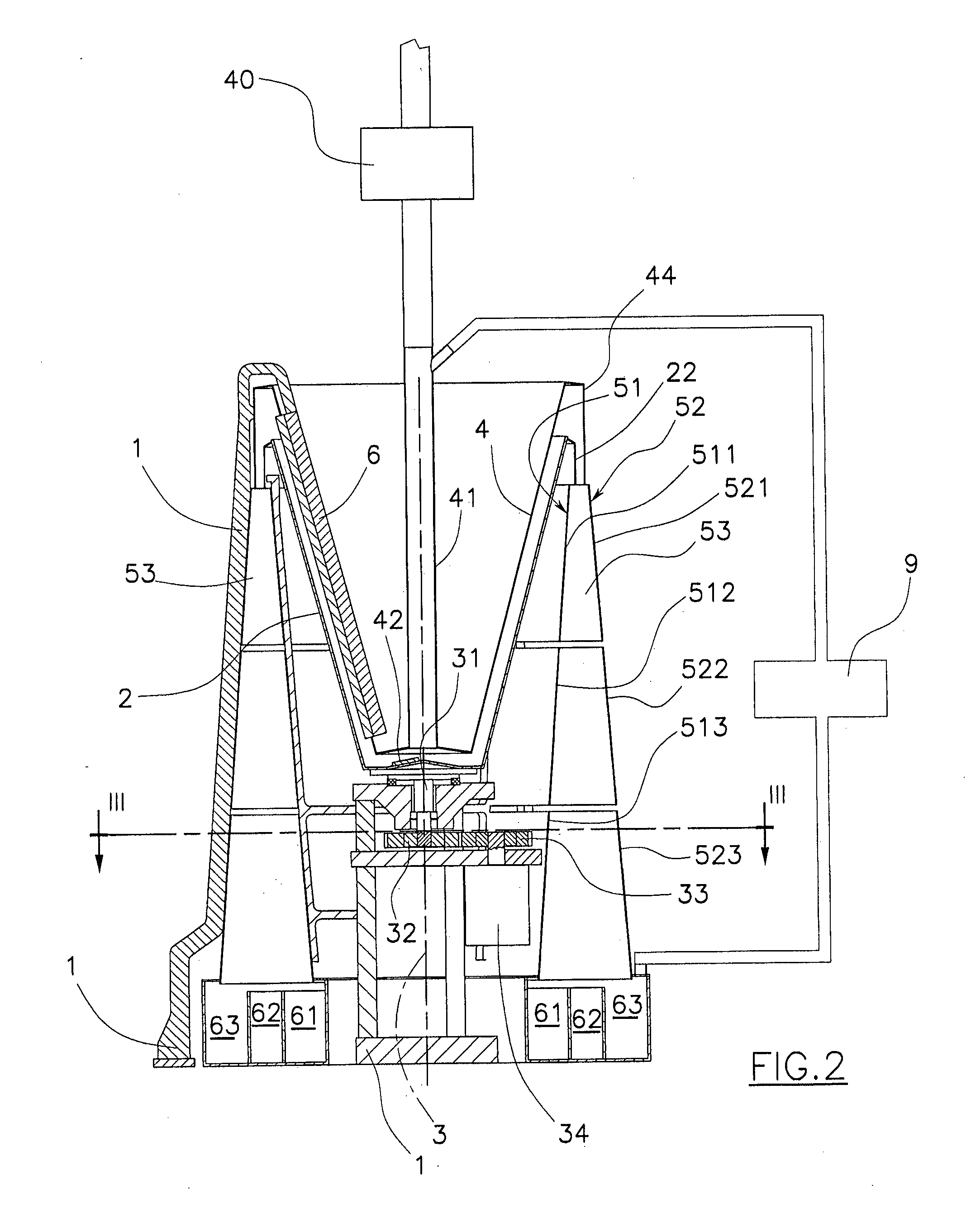
[0141]The mass of granules in the hopper 100 comprises respectively PVC, PP and PTFE granules.

[0142]With the mass of PVC granules to be separated, the internal surface of the tube 300 is clad with PVC and a pile 501 of granules not deviated by the electrical field is obtained, constituted entirely of PVC.


PUM


Abstract

A method for separating a granular synthetic material from a loose mass of various synthetic materials includes: conveying the granular mass along a trajectory having a rubbing surface subjecting the mass falling from the rubbing surface to an electrical field; and collecting at least one of the masses separated by the electrical field. The mass advances in a single layer on the rubbing surface, while maintaining the single layer contact with the rubbing surface, the rubbing surface being subjected to repeated acceleration in opposite directions in the plane of the rubbing surface, or tangential thereto to move the mass on the surface in order to improve the electrostatic charge. The rubbing surface is made of or clad with a material having intermediate triboelectric properties with respect to those of the granular mass, and is clad with a same material as that which it is intended to separate from the mass.

Description

TECHNICAL FIELD[0001]The present invention relates to recuperation of articles made of synthetic material gathered in refuse collection where a principal aim is to use the materials for recycling.BACKGROUND ART[0002]In the prior art recycling is attained by first mincing the articles made of materials that are different from one another, with the aim of obtaining a granular material having an average size in the order of 0.5-25 mm.[0003]The granular material comprises a mass made up of granules of various materials which in order to be re-utilised have to be separated such as to obtain homogeneous masses comprising granules of the same material.[0004]Granule separation techniques are known for plastic materials which use the triboelectric effect, which is based on the following phenomenon.[0005]By causing particles of a first material A to rub against particles of a second material B, particles A and B become electrostatically oppositely charged.[0006]By the same process of rubbing,...

Claims


Application Information

Patent Timeline
Patent Type & Authority Applications(United States)
IPC IPC(8): B03C7/12
CPCB03C7/12B03C7/006
Inventor CASSANI, STEFANO
Owner CASSANI STEFANO
Why Eureka
Try Eureka