Electronic device associated with a photovoltaic module to optimise the throughput of a bidirectional VLC transmission

a photovoltaic module and bidirectional transmission technology, applied in the field of optical communication devices for visible or invisible, infrared (ir) and ultraviolet light, can solve the problems of deterioration of the snr and therefore of the throughput, failure to give satisfactory results in terms of faithful modulation, and inability to process the information that it contains, so as to maximize the throughput of data transmitted

Active Publication Date: 2019-04-16
GARMIN
View PDF6 Cites 1 Cited by
  • Summary
  • Abstract
  • Description
  • Claims
  • Application Information

AI Technical Summary

Benefits of technology

[0019]The main aim of the invention is to describe an electronic device which makes it possible to increase the quality and the level of the electrical signal generated by a photovoltaic module which is illuminated by a modulated light. That makes it possible, on the one hand, to transmit data by this communication mode (VLC) by minimizing the distortion of the signal received and, on the other hand, to dynamically adapt the electrical response of the photovoltaic module as a function of the frequency and / or modulation characteristics of the lights that it receives, in order to increase the throughput of the data transmitted.SUBJECTS OF THE INVENTION
[0027]of a processing module for the signal generated by said photodetector capable of communicating with the control means via a return channel;said wireless communication device is characterized in that the reception module further comprises an electronic means situated between the photodetector and the signal processing module and capable of matching the impedance of the photodetector in order to maximize the signal-to-noise ratio of the modulated electrical signal by minimizing the distortions of said modulated electrical signal linked to a poor impedance matching at the output of the photodetector, while maximizing the level of the modulated electrical signal and the throughput of transmitted data.
[0036]In another particular embodiment, the visible light communication device according to the invention comprises a plurality of emission modules which emit modulated lights with different modulation characteristics, the photodetector being incorporated in a mobile object which successively receives one or other of said modulated lights and having an electronic impedance matching means capable of maximizing the throughput of data transmitted by each of said emission modules.

Problems solved by technology

In order, at each instant, to extract the best modulated signal, it is necessary to introduce an impedance matching stage between the photovoltaic module and the signal processing module in order to couple the two elements as perfectly as possible; however, the known devices allowing an impedance matching are not suitable (because they are designed to extract the maximum of power), and do not therefore give satisfactory results in terms of faithful translation of the modulated light signal received by the photovoltaic module.
When the load impedance of a photovoltaic module is not optimized, the analog electrical signal generated by the photovoltaic module is either too distorted for the information that it contains to be able to be processed, or too weak to be processed by the signal processing module.
On the other hand, if the signal has not been correctly restored because, for example, of a poor impedance matching of the photodetector, the TIA, whose function is not to match the impedance in order to correct the distortion of the electrical signal, will only amplify the distorted signal, causing a deterioration of the SNR and therefore of the throughput.

Method used


Image

  • Electronic device associated with a photovoltaic module to optimise the throughput of a bidirectional VLC transmission
  • Electronic device associated with a photovoltaic module to optimise the throughput of a bidirectional VLC transmission
  • Electronic device associated with a photovoltaic module to optimise the throughput of a bidirectional VLC transmission

Examples


Embodiment Construction

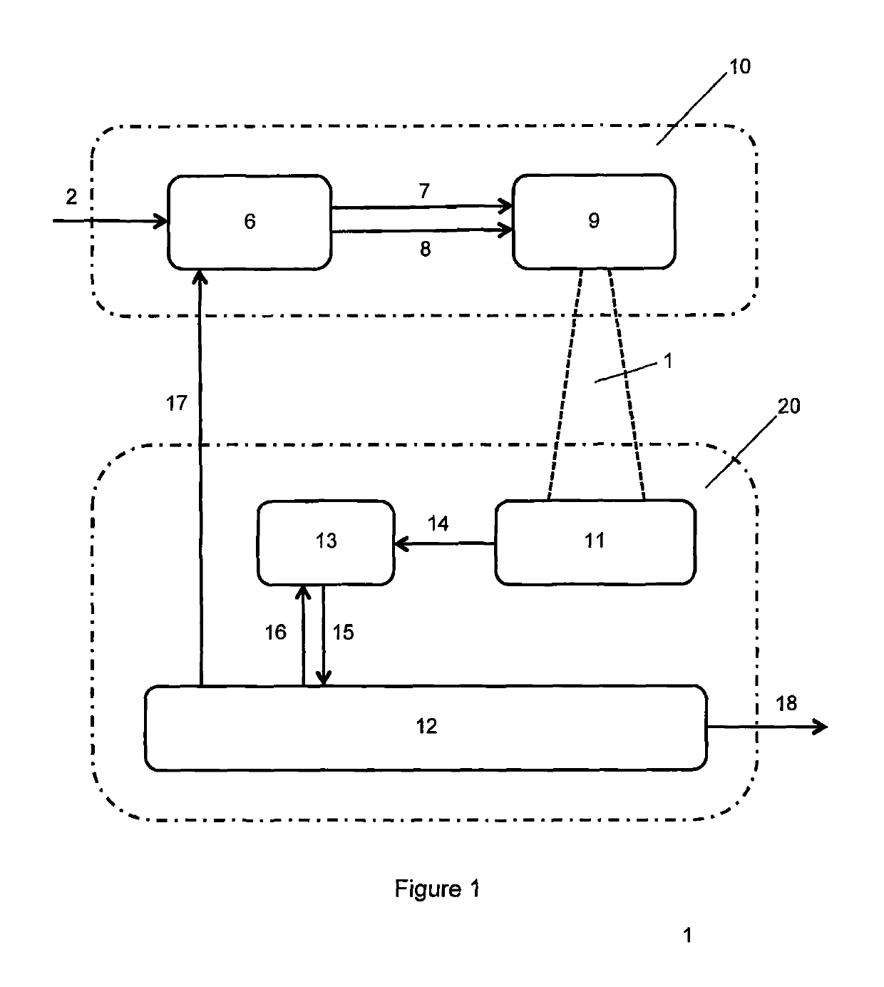
[0062]Refer to FIG. 1, which is a diagram of the bidirectional wireless communication device that is the subject of the invention. This device comprises an emission module 10 and a reception module 20. The emission module 10 makes it possible to encode source digital data 2, for example from the internet, to transmit them in the form of an amplitude—and / or phase-modulated light 1. For this, the light source 9, such as a light-emitting diode, is powered by a control means 6 which generates an electrical signal generally comprising a direct component 7 and an alternating component 8. The direct component 7 is used to bias said light-emitting diode 9 in order to produce the lighting function, and the alternating component 8 is derived from the digital / analog conversion of the source data 2. The reception module 20 is composed of a photodetector such as a photovoltaic module 11 which transforms the modulated light 1 into a modulated electrical signal 14, an electronic means 13 for match...


PUM


Abstract

The invention relates to a bidirectional wireless communication device which is based on the use of light, including emitting modules, each emitting amplitude- and / or phase-modulated light; and a receiving module made up of: a photodetector illuminated by said modulated light and generating a modulated electrical signal in response to said modulated light; and a processing module for processing the signal generated by said photodetector. The receiving module includes an electronic means positioned between the photodetector and the signal-processing module and capable of matching the impedance of the photodetector to maximize the signal-to-noise ratio of the electrical signal by minimizing distortions of said electronic signal associated with incorrect impedance matching at the output of the photodetector, while maximizing the level of the modulated electrical signal and the throughput of transmitted data.

Description

TECHNICAL FIELD OF THE INVENTION[0001]The present invention relates to visible or invisible, infrared (IR) and ultraviolet (UV) light communication devices, in the context of the optimization of the throughput of the data transmitted.STATE OF THE ART[0002]The visible light communication devices (VLC or LiFi, acronyms respectively standing for “visible light communication” and “light fidelity”) use the visible light to transmit information between two distant points. The visible light communication systems generally comprise one or more light-emitting diodes (LEDs) forming an emission means and a photodetector forming a reception means. The LED supplies a light signal in the visible whose intensity is modulated as a function of the data to be transmitted. LED luminaires offer the advantage of allowing the dual function of lighting and of data transmission. Their physical characteristics make it possible to consider data transmission throughputs with throughputs of the order of a giga...

Claims


Application Information

Patent Timeline
Patent Type & Authority Patents(United States)
IPC IPC(8): H04B10/54H04B10/116H04B10/58H04B10/114H04B10/69
CPCH04B10/697H04B10/116H04B10/1141H04B10/691H04B10/54H04B10/58H04B10/1143
Inventor AVELINE, FRANCKBIALIC, EMILIECHAUMONT, NICOLAS
Owner GARMIN
Why Eureka
Try Eureka