

Method for providing illuminated components and components formed from the method
a technology of components and methods, applied in the field of illumination structures, can solve the problems of inability to offer a simulated stitch with a changing color or illumination, and achieve the effect of not being able to produce a product with illumination or a change of color
- Summary
- Abstract
- Description
- Claims
- Application Information
AI Technical Summary
Benefits of technology
Problems solved by technology
Method used
Image

Examples
Embodiment Construction
[0020]Various embodiments of the present invention are directed to alternative means of adding accent lighting to an article of manufacture and in one non-limiting embodiment, an automotive vehicle interior by integrating lighting as part of the sewing operation. Various embodiments of the invention are also applicable to any and all industries which manufacture a product containing a decorative and / or functional stitch.
[0021]One embodiment described herein proposes the use of the sewing process to incorporate accent lighting to a vehicle interior. In accordance, with exemplary embodiments of the present invention accent lighting can be sewn into a component using, but not limited to, one of the following methods:
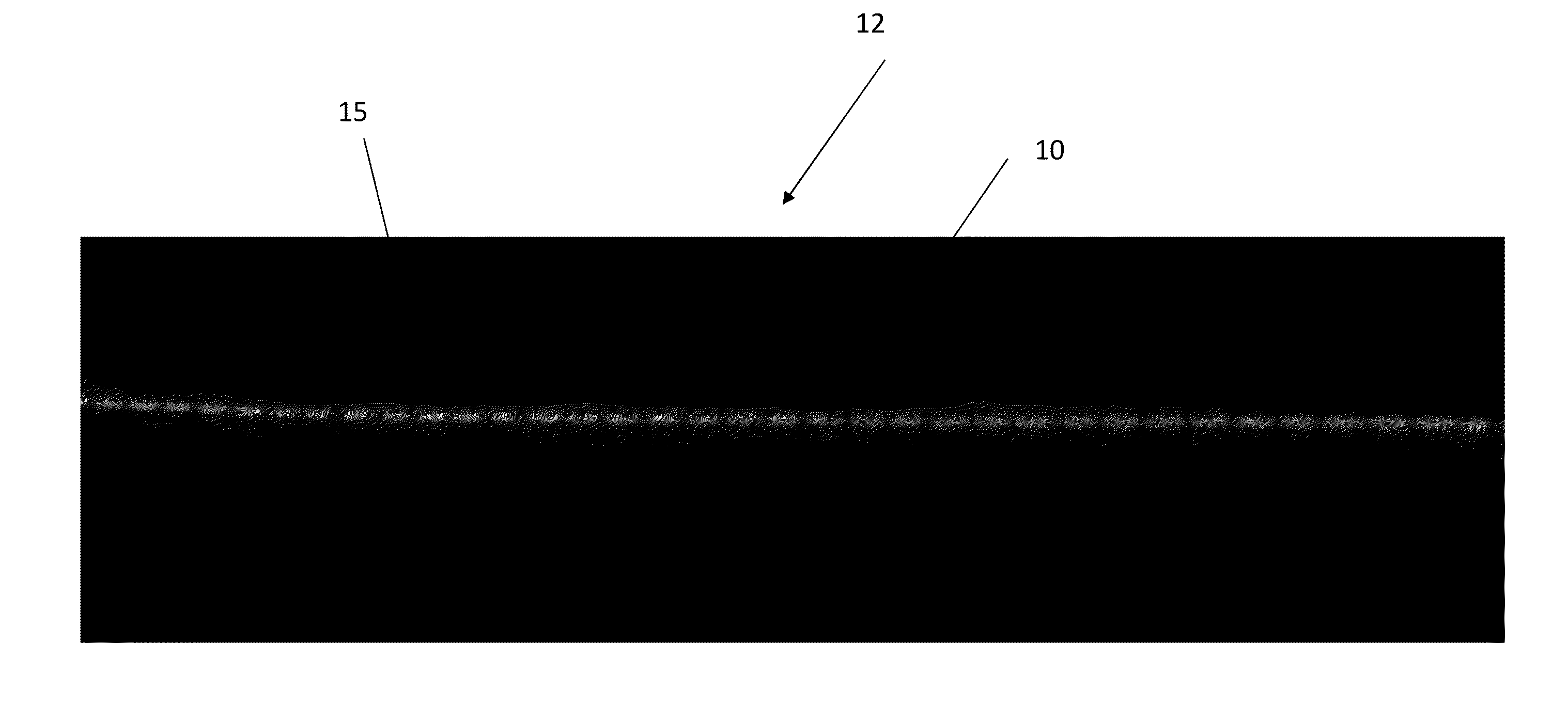
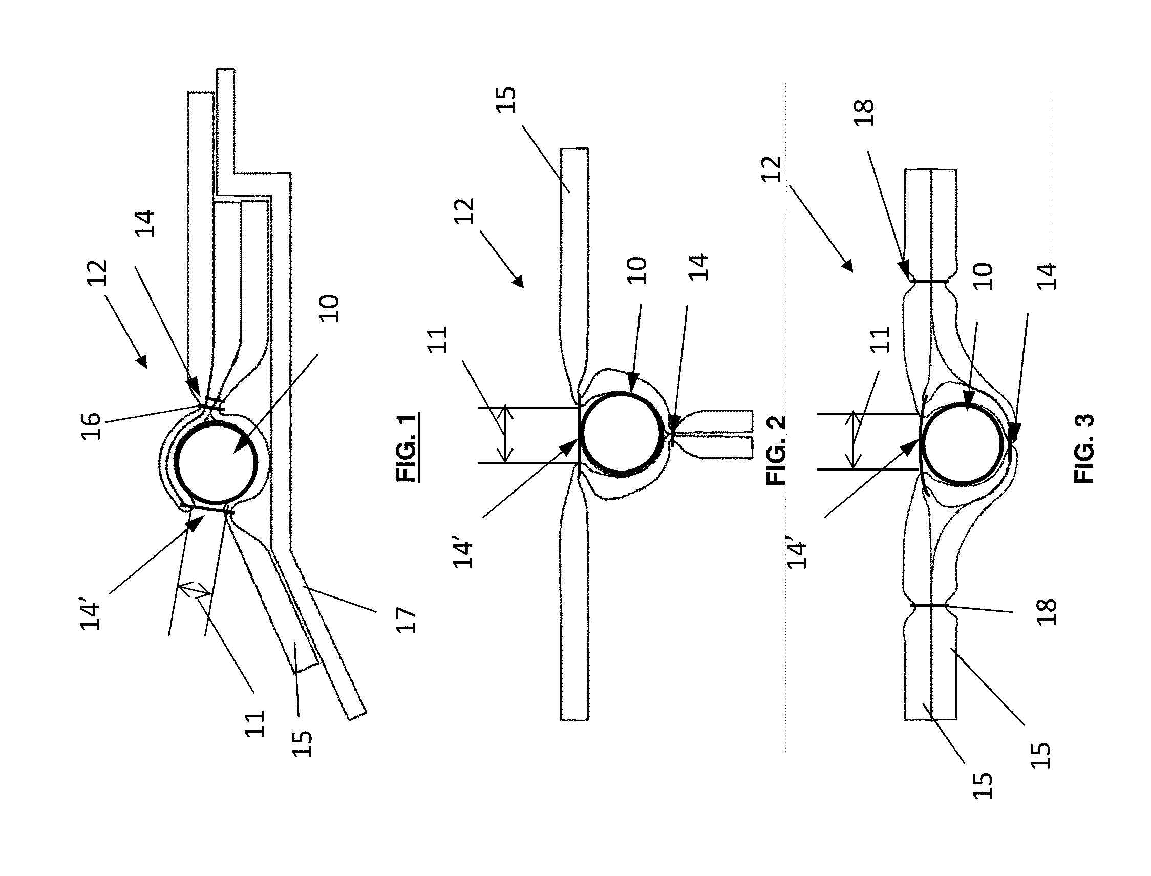
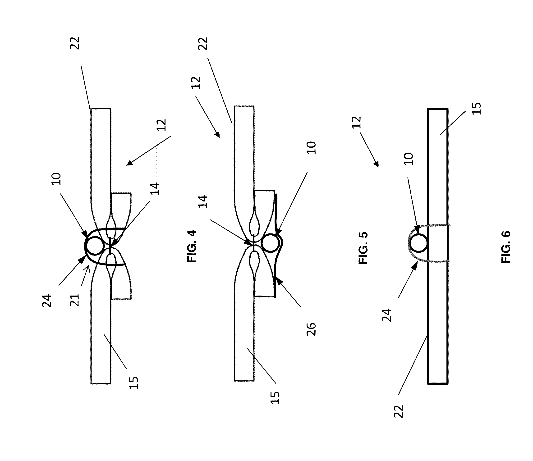
[0022]1) Use of a light pipe, fiber optic cable, or other light conducting medium and / or generating medium as a thread that is sewn into a trim component that produces an illuminated stitch when connected to a light source.
[0023]When the lighting source is used as a thread ...
PUM
 Abstract
Description
Claims
Application Information