Attachment structure for attachment of component to article and electric junction box having thereof
a technology of attachment structure and component, which is applied in the direction of machine supports, application, coupling device connections, etc., can solve the problem that the electric junction box can only attach those components, and achieve the effect of improving space efficiency, simple and versatile construction, and smooth insertion into the guide portions
- Summary
- Abstract
- Description
- Claims
- Application Information
AI Technical Summary
Benefits of technology
Problems solved by technology
Method used
Image
Examples
first embodiment
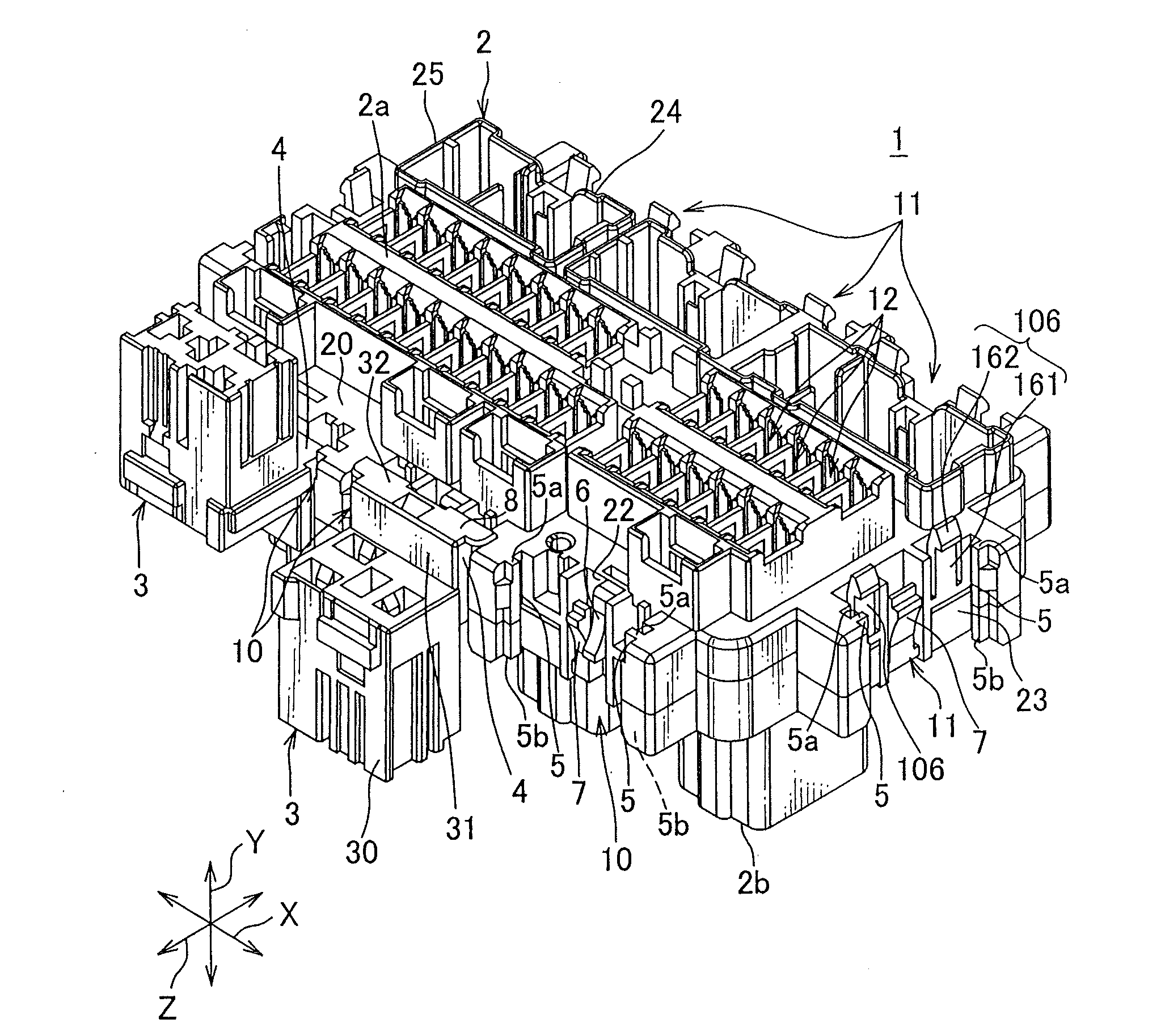
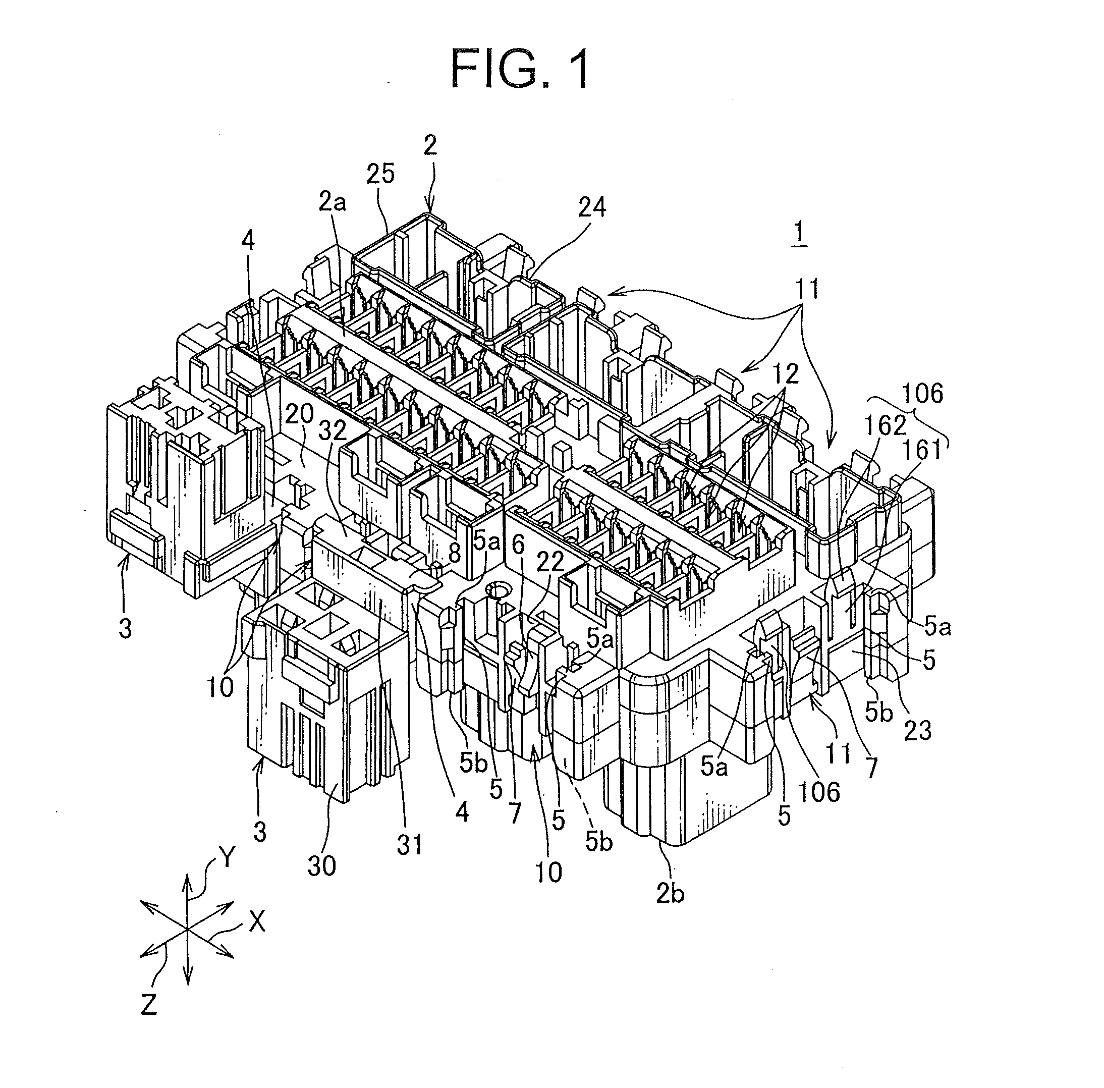
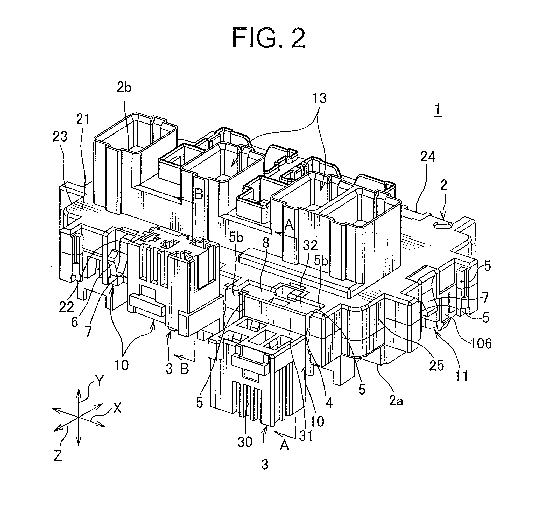
[0038]“An attachment structure 1 of an article and a component” according to a first embodiment of the present invention will be explained with reference to FIGS. 1 to 8. “The attachment structure 1 of the article and the component” constructs “an electric junction box” mounted on a vehicle. The electric junction box supplies electric power with electronic devices mounted on the vehicle, and transfers a signal thereto. Incidentally, the electric junction box is referred to as a junction block, a junction box, a fuse block, a fuse box, a relay block, or a relay box. In this description, these junction blocks, the junction box, the fuse block, the fuse box, the relay block and the relay box are collectively called the electric junction box hereafter.
[0039]As shown in FIGS. 1 and 2, the above “attachment structure 1 of the article and the component” is an attachment structure attaching a component 3 to a plastic case 2 as the article.
[0040]As shown in FIGS. 7 and 8, the above component...
second embodiment
[0056]Next, “an attachment structure 101 of an article and a component” according to a second embodiment of the present invention will be explained with reference to FIGS. 9 to 14. In FIGS. 9 to 14, components already described with reference to the first embodiment are denoted by the same reference numerals, and thus detailed description thereof will be hereinafter omitted. Furthermore, “the attachment structure 101 of the article and the component” of the second embodiment of the present invention constructs “an electric junction box” mounted on a vehicle in the same manner as the first embodiment.
[0057]As shown in FIGS. 9 and 10, the above “the attachment structure 101 of the article and the component” is an attachment structure attaching components 3 and 103 to a plastic case 102 as the article.
[0058]The component 103 is a connector connected to a relay 19 as shown in FIGS. 9 and 10. A figure of an electric wire connected to the connector is omitted. The component 103 includes a...
third embodiment
[0062]Next, “an attachment structure 201 of an article and a component” according to a third embodiment of the present invention will be explained with reference to FIGS. 15 to 19. In FIGS. 15 to 19, components already described with reference to the first embodiment are denoted by the same reference numerals, and thus detailed description thereof will be hereinafter omitted. Furthermore, “the attachment structure 201 of the article and the component” of the third embodiment of the present invention constructs “an electric junction box” mounted on a vehicle in the same manner as the first and second embodiments.
[0063]As shown in FIG. 15, the above “attachment structure 201 of the article and the component” is an attachment structure attaching a component 203 to a plastic case 202 as the article.
[0064]The component 203 is a connector connected to the relay 18 as shown in FIG. 17. A figure of an electric wire connected to the connector is omitted. The component 203 includes the joint ...
PUM
 Abstract
Description
Claims
Application Information
 - R&D
- Intellectual Property
- Life Sciences
- Materials
- Tech Scout
- Unparalleled Data Quality
- Higher Quality Content
- 60% Fewer Hallucinations
Browse by: Latest US Patents, China's latest patents, Technical Efficacy Thesaurus, Application Domain, Technology Topic, Popular Technical Reports.
© 2025 PatSnap. All rights reserved.Legal|Privacy policy|Modern Slavery Act Transparency Statement|Sitemap|About US| Contact US: help@patsnap.com


