Boot hanger mounting bracket

a technology for mounting brackets and boots, which is applied in the field of duct systems, register boots, and register boots, can solve the problems of large quantity of space per unit to store and transport, difficult to store, handle and transport connections and fittings, and insecure mounting or mounting at odd angles, etc., to achieve the effect of simple and versatile construction, quick and easy assembly, and reduced costs

Inactive Publication Date: 2005-03-15
APPLIED APPL INT LLC
View PDF22 Cites 21 Cited by
  • Summary
  • Abstract
  • Description
  • Claims
  • Application Information

AI Technical Summary

Benefits of technology

It is an object of the present invention to overcome the above and other drawbacks by providing an assembly to support and mount ductwork components of heating, cooling and ventilation systems. The assembly has a simple and versatile construction and can be quickly and easily assembled. Further, the assembly may be stored and transported in a flattened state, and can be adjusted on-site to provide an accurate fit between the boot register, grille and wall, floor or ceiling opening, which reduces costs.
It is a further object of the invention to produce a mounting bracket that allows adjustable installation and allows the register grille to be placed in close proximate fit to both the ductwork and the ceiling or wall in which the register grille is installed so that gaps may be minimized.

Problems solved by technology

Because the grilles generally must be mounted to the wall studs or ceiling joists, or to the ducts themselves, there is a risk that the grilles may be insecurely mounted or mounted at odd angles, particularly where the grilles are first attached and subsequently temporarily removed for wall painting or cleaning or other purposes.
First, the connections and fittings are difficult to store, handle, and transport without incurring damage.
In addition, due to their shape and design, they require a large quantity of space per unit to store and transport.
These problems cause the production of excessive scrap and increased inventory holding and transportation costs for the distributor and customers.
Additionally, the configuration of the ductwork and grilles poses a problem for unskilled construction workers and is extremely time consuming.
Because any measurements can introduce inaccuracies, the possibility that the components will not fit together or provide support for the grille register and boot in the wall or ceiling opening or create gaps between the edges of the opening and the grille register is a real concern.

Method used


Image

  • Boot hanger mounting bracket
  • Boot hanger mounting bracket
  • Boot hanger mounting bracket

Examples


Embodiment Construction

)

The detailed description set forth below in connection with the appended drawings is intended as a description of presently-preferred embodiments of the invention and is not intended to represent the only forms in which the present invention may be constructed and / or utilized. The description sets forth the functions and the sequence of steps for constructing and operating the invention in connection with the illustrated embodiments. However, it is to be understood that the same or equivalent functions and sequences may be accomplished by different embodiments that are also intended to be encompassed within the spirit and scope of the invention.

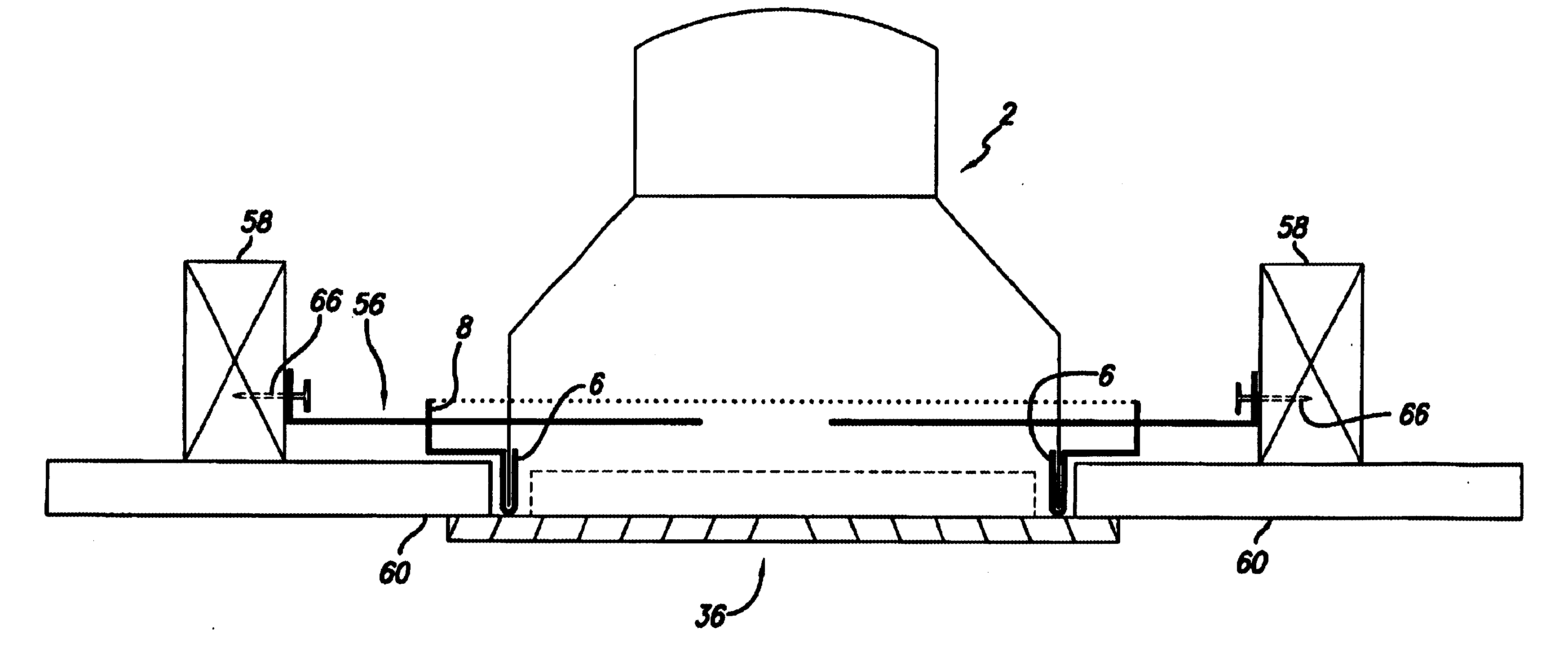
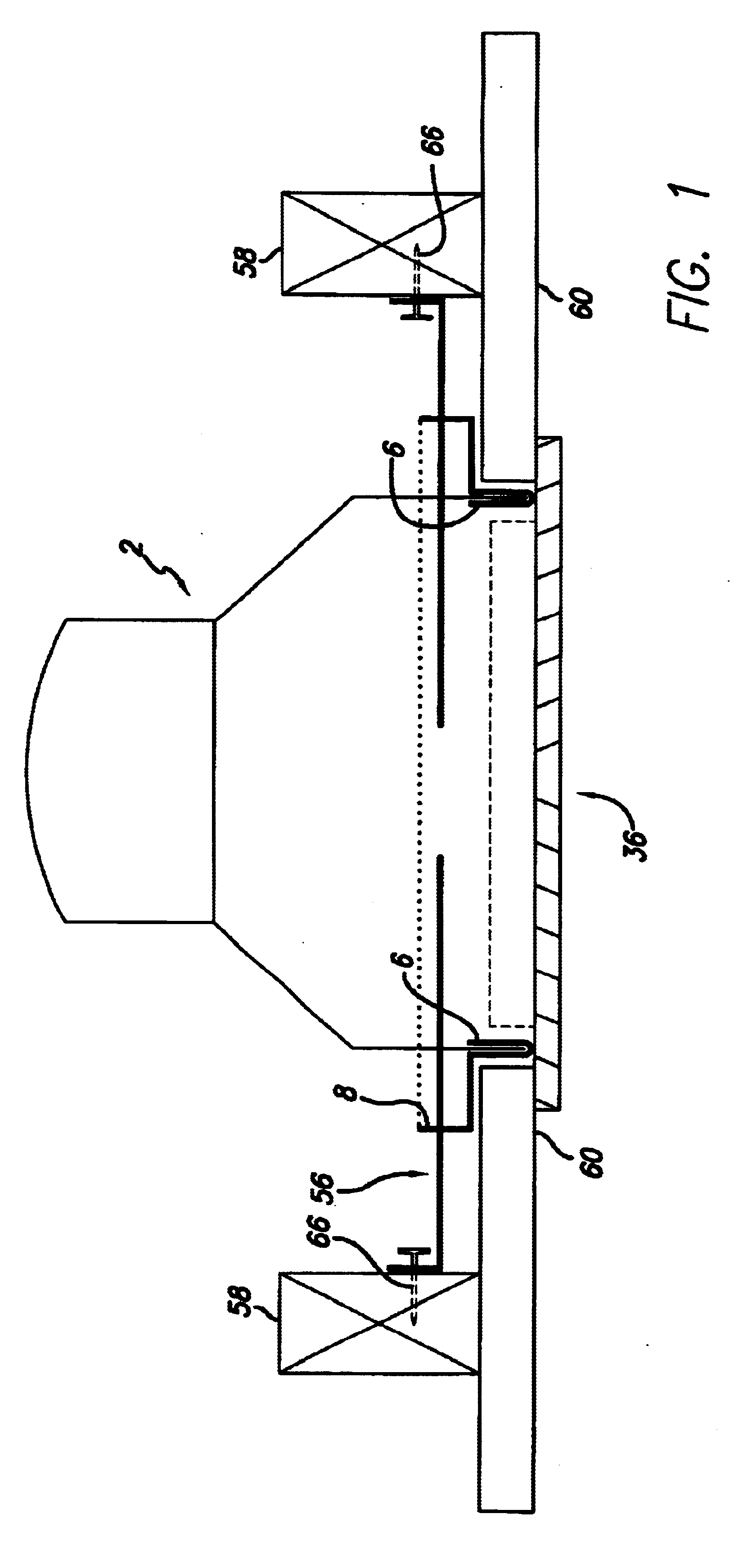
Turning now to FIGS. 1 to 13 of the drawings, and more particularly to FIG. 1, the typical environment which the present invention is operated is illustrated. As shown in FIG. 1, a typical vertical ceiling joist 58 is shown. Although FIG. 1 illustrates the present invention mounted in a ceiling, it is contemplated that the present invention ...


PUM


Abstract

The present invention relates to duct systems, registers and ductwork components used with floor or ceiling registers employed in warm air heating, ventilating and air conditioning systems, and specifically to improvements for mounting and installing the components of the duct system, including register boots, mud rings and register grilles, in the walls, floors or ceilings of buildings.The invention includes an adjustable boot hanger mounting bracket assembly comprising a boot hanger frame portion and a support member portion; the ductwork components, which may include a pre-fabricated can-boot / mud ring assembly; a pair of boot hanger arms; and a register grille. The boot hanger mounting bracket assembly is formed of a sturdy yet bendable material so that it can be configured and adjusted on-site. Once configured, the boot hanger mounting bracket assembly is secured to the building structure by securing a pair of boot hanger arms to the ceiling joists, wall studs or other support structure. In this way, the boot hanger mounting bracket, through a direct attachment to the ceiling joist or wall stud, provides a positive inexpensive simple and error free way to mount the duct components.

Description

BACKGROUND OF THE INVENTION1. Field of the InventionThis invention relates to duct systems, registers and register boots, used as air ducts for warm air heating, ventilating and air conditioning systems, and specifically to improvements for mounting and installing the components of the duct system, including register boots, mud rings and air registers, in the walls, floors or ceilings of buildings.2. Description of the Related ArtForced air heating, cooling and ventilation systems, or “HVAC systems” are designed to provide control of space temperature, humidity, air contamination, differential pressurization, and air motion. These distribution systems use a network of ducts to deliver the heated and / or cooled air to the various rooms and spaces within a building structure. Of the many HVAC systems currently available, galvanized sheet steel duct systems are among the most widely used. These systems generally consist of an air heating and / or refrigeration unit, straight sections of d...

Claims


Application Information

Patent Timeline
Patent Type & Authority Patents(United States)
IPC IPC(8): F24F13/02F24F13/06
CPCF24F13/02F24F13/06F24F13/0254
Inventor PILGER, ALLAN
Owner APPLIED APPL INT LLC
Why Eureka
Try Eureka