Attachment structure for attachment of component to article and electric junction box having thereof

a technology of attachment structure and component, which is applied in the direction of machine supports, application, coupling device connections, etc., can solve the problem that the electric junction box can only attach those components, and achieve the effect of improving space efficiency, simple and versatile construction, and smooth insertion into the guide portions

Active Publication Date: 2013-04-23
YAZAKI CORP
View PDF4 Cites 5 Cited by
  • Summary
  • Abstract
  • Description
  • Claims
  • Application Information

AI Technical Summary

Benefits of technology

[0014]According to the first aspect of the present invention, the component can be attached to the article in both one direction and a direction opposite to the one direction. More specifically, the component can be attached to the article in the state where the slide portion is inserted in a space between the pair of the guide portions from the one end of the article and slides toward the other end of the article. Also, the component can be attached to the article in the state where the slide portion is inserted in the space between the pair of the guide portions from the other end of the article in a posture opposite to that in which the slide portion is inserted between the pair of the guide portions from the one end of the article.
[0015]According to the second aspect of the present invention, the attachment structure having simple and versatile construction can be provided.
[0016]According to the third aspect of the present invention, when the slide portion is inserted between the pair of the guide portions from the one end of the article, the projection can be prevented from being caught on the second locking portion. Furthermore, the slide portion can be smoothly inserted into the guide portions.
[0017]According to the fourth aspect of the present invention, the electric junction box which is able to improve space efficiency and to design an optimum layout in a vehicle can be provided

Problems solved by technology

However, the electric junction box can only attach those components in a predetermined direction, namely, one position.
Further, this problem occurs similarly in the attachment structure of the article other than the case and the components.[Patent Document 1] JP, A, H11-234851

Method used


Image

  • Attachment structure for attachment of component to article and electric junction box having thereof
  • Attachment structure for attachment of component to article and electric junction box having thereof
  • Attachment structure for attachment of component to article and electric junction box having thereof

Examples


first embodiment

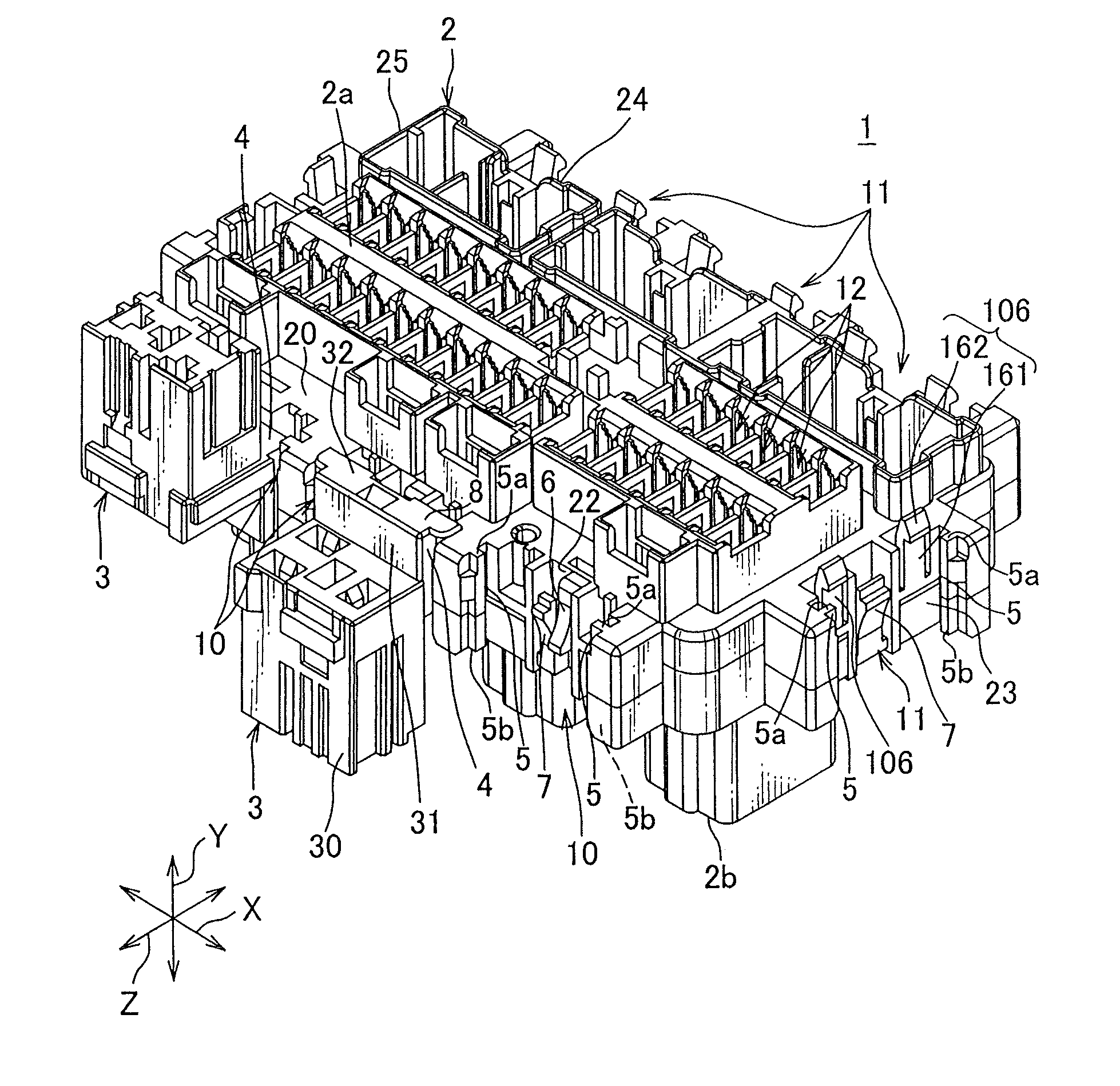
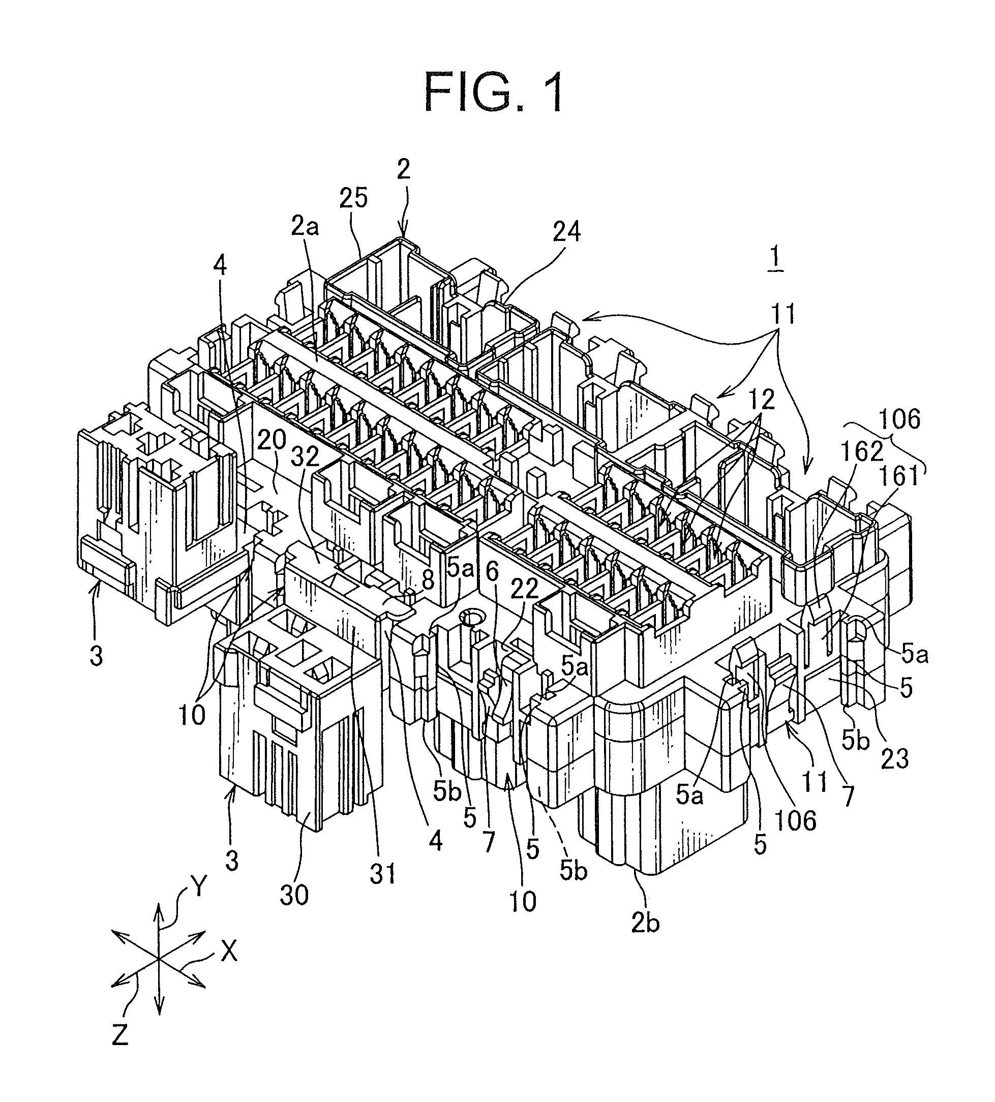
[0038]“An attachment structure 1 of an article and a component” according to a first embodiment of the present invention will be explained with reference to FIGS. 1 to 8. “The attachment structure 1 of the article and the component” constructs “an electric junction box” mounted on a vehicle. The electric junction box supplies electric power with electronic devices mounted on the vehicle, and transfers a signal thereto. Incidentally, the electric junction box is referred to as a junction block, a junction box, a fuse block, a fuse box, a relay block, or a relay box. In this description, these junction blocks, the junction box, the fuse block, the fuse box, the relay block and the relay box are collectively called the electric junction box hereafter.

[0039]As shown in FIGS. 1 and 2, the above “attachment structure 1 of the article and the component” is an attachment structure attaching a component 3 to a plastic case 2 as the article.

[0040]As shown in FIGS. 7 and 8, the above component...

second embodiment

[0056]Next, “an attachment structure 101 of an article and a component” according to a second embodiment of the present invention will be explained with reference to FIGS. 9 to 14. In FIGS. 9 to 14, components already described with reference to the first embodiment are denoted by the same reference numerals, and thus detailed description thereof will be hereinafter omitted. Furthermore, “the attachment structure 101 of the article and the component” of the second embodiment of the present invention constructs “an electric junction box” mounted on a vehicle in the same manner as the first embodiment.

[0057]As shown in FIGS. 9 and 10, the above “the attachment structure 101 of the article and the component” is an attachment structure attaching components 3 and 103 to a plastic case 102 as the article.

[0058]The component 103 is a connector connected to a relay 19 as shown in FIGS. 9 and 10. A figure of an electric wire connected to the connector is omitted. The component 103 includes a...

third embodiment

[0062]Next, “an attachment structure 201 of an article and a component” according to a third embodiment of the present invention will be explained with reference to FIGS. 15 to 19. In FIGS. 15 to 19, components already described with reference to the first embodiment are denoted by the same reference numerals, and thus detailed description thereof will be hereinafter omitted. Furthermore, “the attachment structure 201 of the article and the component” of the third embodiment of the present invention constructs “an electric junction box” mounted on a vehicle in the same manner as the first and second embodiments.

[0063]As shown in FIG. 15, the above “attachment structure 201 of the article and the component” is an attachment structure attaching a component 203 to a plastic case 202 as the article.

[0064]The component 203 is a connector connected to the relay 18 as shown in FIG. 17. A figure of an electric wire connected to the connector is omitted. The component 203 includes the joint ...


PUM


Abstract

The attachment structure for attachment of a component to an article in two postures includes a case as the article and the component. The case includes a pair of guide portions, first locking arms and a second locking arm. The component includes a slide portion between the guide portions, a stopper arranged in an end of the slide portion and formed in a size which is not able to insert stopper between the guide portions. The first locking arm is engaged where the slide portion is inserted in a space between the guide portions from one end and slides toward an other end. The second locking arm is engaged where the slide portion is inserted in the space between the guide portions from the other end in a posture opposite to that in which the slide portion is inserted between the pair of the guide portions from the one end.

Description

[0001]This application claims priority benefit of Japan Patent Application No. 2011-219868 and the full content of that application is incorporated by reference.BACKGROUND OF THE INVENTION[0002]1. Field of the Invention[0003]The present invention relates to attachment structure for attachment of a component to an article and an electric junction box having the attachment structure.[0004]2. Description of the Related Art[0005]Various electric devices are mounted on a vehicle. In the vehicle, an electric junction box is arranged in a suitable place between an electric wire and the electronic device so as to supply electric power with the various electronic devices. Various electric junction boxes are used depending on the type of vehicle. For example, as an electric junction box disclosed in the Patent Document 1, a plurality of an attachment portions which is able to attach various components are provided.[0006]The electric junction box disclosed in Patent Document 1 can improve arra...

Claims


Application Information

Patent Timeline
Patent Type & Authority Patents(United States)
IPC IPC(8): H01R13/502
CPCH01R13/73B60R16/0238H01R9/2408H01R13/506
Inventor HIRASAWA, HITOSHITAKAHASHI, HIROAKINAKAYAMA, MAKOTOMITSUI, TAKAHIKO
Owner YAZAKI CORP
Why Eureka
Try Eureka