Sliding cable and control cable

Active Publication Date: 2013-04-11
SHIMANO INC +1
View PDF11 Cites 3 Cited by
  • Summary
  • Abstract
  • Description
  • Claims
  • Application Information

AI Technical Summary

Benefits of technology

[0006]The conventional sliding cable can reduce the sliding resistance. However, when grease or another lubricant is disposed in an interior of the cable main body, there is a possibility that the lubricant wil

Problems solved by technology

However, when grease or another lubricant is disposed in an interior of the cable main body, there is a possibility that the lubricant w

Method used


Image

  • Sliding cable and control cable
  • Sliding cable and control cable
  • Sliding cable and control cable

Examples


Example

[0016]Selected embodiments will now be explained with reference to the drawings. It will be apparent to those skilled in the art from this disclosure that the following descriptions of the embodiments are provided fOr illustration only and not for the purpose of limiting the invention as defined by the appended claims and their equivalents.

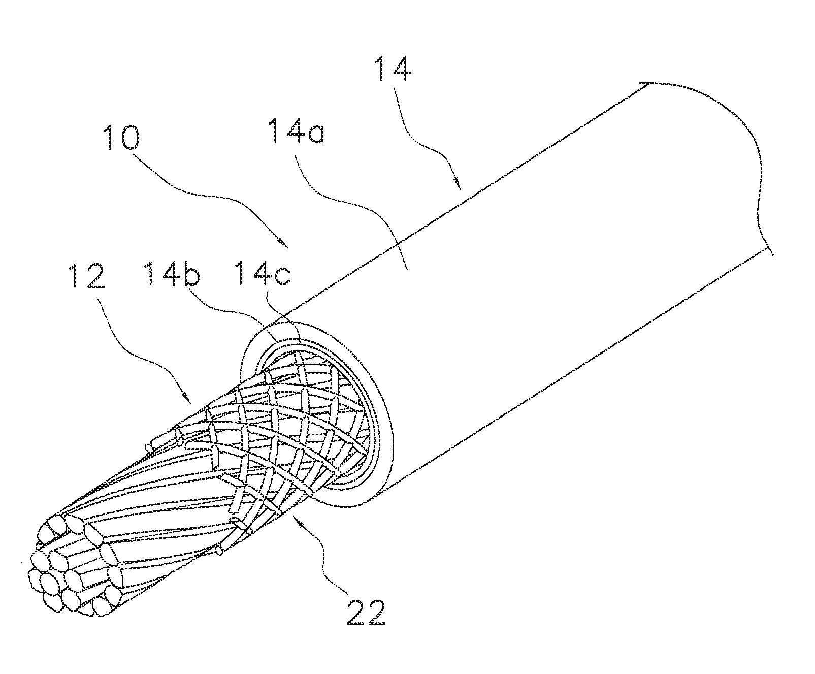
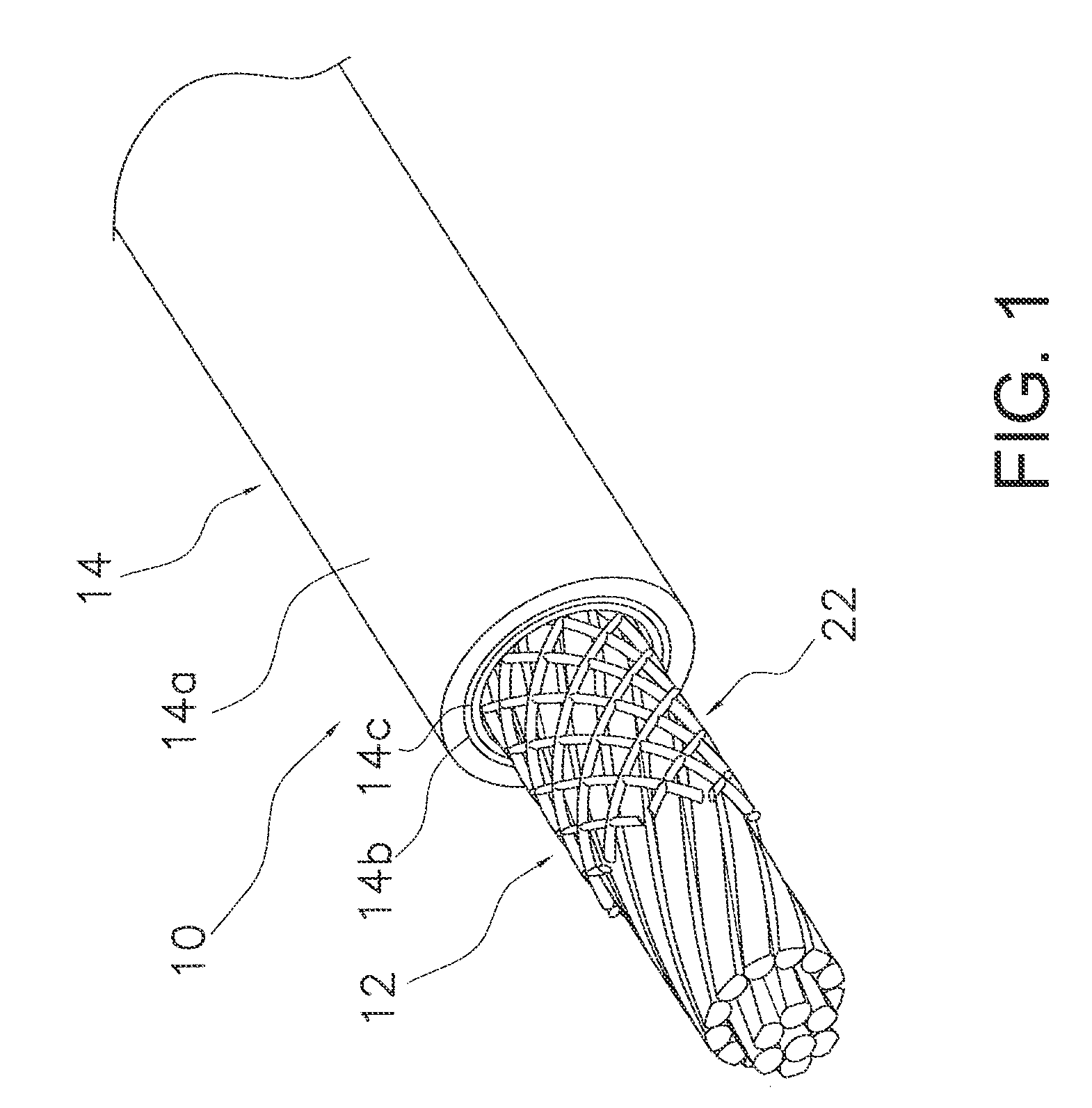
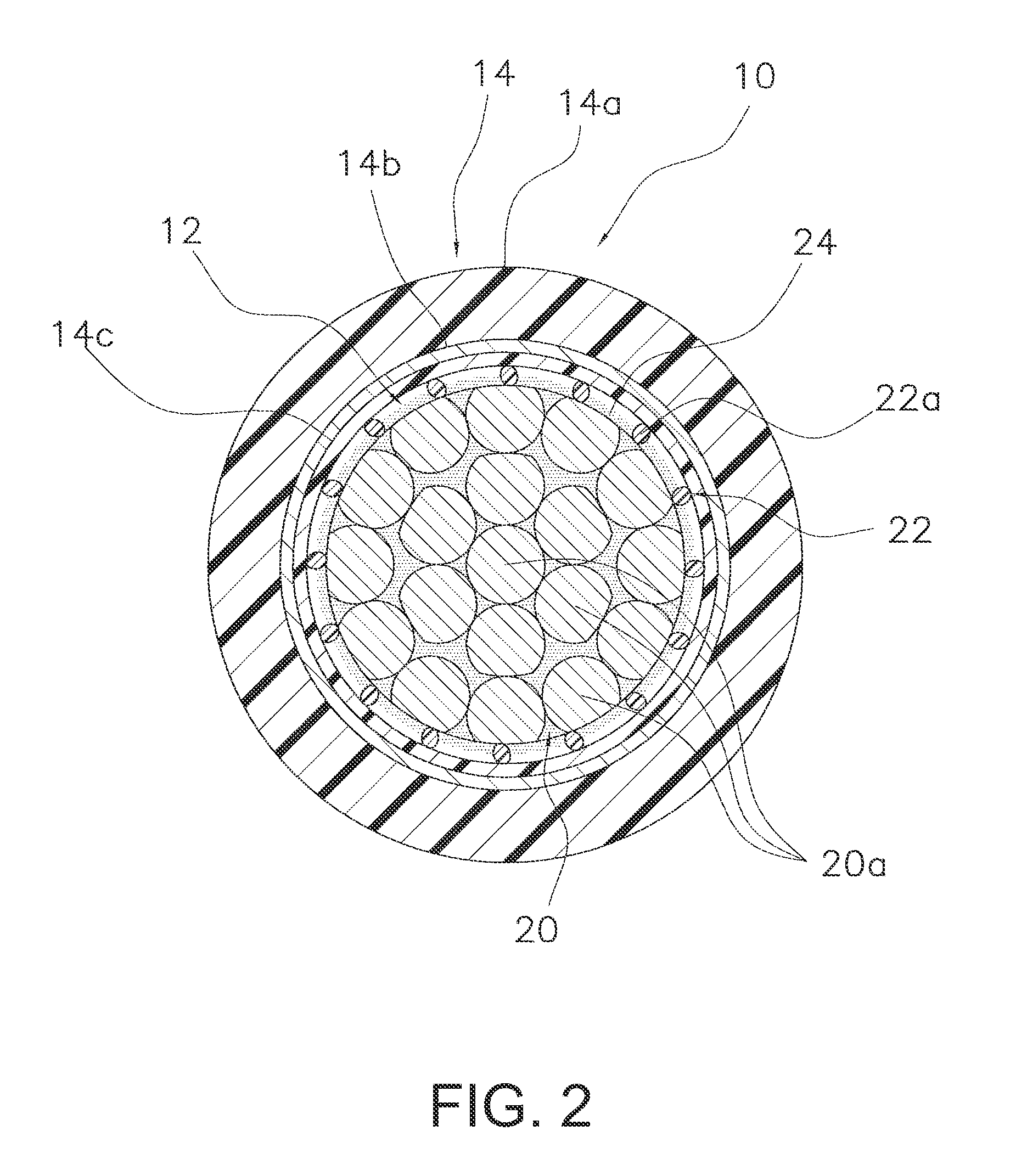
[0017]FIGS. 1 and 2 show a sliding cable according to one embodiment of the present invention. The sliding cable is used in a control cable 10 for controlling, for example, a braking device, a transmission, or a suspension of a bicycle. The control cable 10 has a sliding cable 12 and an outer casing 14. Thus, the control cable 10 is in the form of a Bowden-type cable.

[0018]As shown in FIGS. 2 and 3, the sliding cable 12 comprises a cable main body 20 and a mesh structural body 22. The cable main body 20 is made up of a plurality of steel wires 20a. The steel wires 20a are bundled together in a spiral fashion. The mesh structural body 22 is arrange...


PUM


Abstract

A sliding cable is provided that basically includes a cable main body and a mesh structural body. The cable main body is made of a plurality of steel wires bundled together. The mesh structural body is arranged on an outer surface of the cable main body.

Description

CROSS-REFERENCE TO RELATED APPLICATIONS[0001]This application claims priority under 35 U.S.C. § 119 to Japanese Patent Application No. 2011-222626, filed Oct. 7, 2011. The entire disclosure of Japanese Patent Application No. 2011-222626 is hereby incorporated herein by reference.BACKGROUND[0002]1. Field of the Invention[0003]This invention generally relates to a cable. More specifically, the present invention relates to a sliding cable that slides inside a casing and a control cable that comprises the sliding cable.[0004]2. Background Information[0005]Bicycles and other transportation devices use sliding cables to operate component parts. A sliding cable is a cable that moves inside a casing. A conventionally known sliding cable has a cable main body comprising steel wires bundled together and a protruding section formed on a surface of the cable main body (e.g., Japanese Laid-Open Patent Publication No. 2004-19732). The conventional sliding cable has a cable main body and an outer ...

Claims


Application Information

Patent Timeline
IPC IPC(8): F16C1/20B62K23/00
CPCF16C1/20Y10T74/20456F16C1/205D07B5/005D07B2201/2002D07B2201/209
Inventor NISHIMURA, ATSUHIROOSE, KENJIASAKAWA, TAKAMOTOTSUKADA, SHOICHINAGAI, YOSHIYUKINISHIYA, KOJI
Owner SHIMANO INC
Why Eureka
Try Eureka