Hydraulic rotary machine and valve plate thereof

Inactive Publication Date: 2019-05-16
KYB CORP
View PDF0 Cites 0 Cited by
  • Summary
  • Abstract
  • Description
  • Claims
  • Application Information

AI Technical Summary

Benefits of technology

[0004]In some hydraulic rotary machines, a surface of a sliding member is coated with a

Problems solved by technology

However, when the surface of the sliding member is coated with the resin

Method used


Image

  • Hydraulic rotary machine and valve plate thereof
  • Hydraulic rotary machine and valve plate thereof
  • Hydraulic rotary machine and valve plate thereof

Examples


Example

First Embodiment

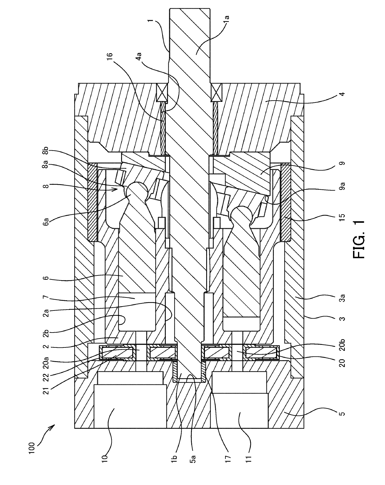
[0019]First, by referring to FIGS. 1 to 7, a hydraulic rotary machine according to a first embodiment of the present invention will be described.

[0020]In the first embodiment, a case where the hydraulic rotary machine is a water-pressure rotary machine 100 using water as an operating liquid will be described. The water-pressure rotary machine 100 functions as a piston pump capable of supplying water as the operating fluid when a shaft 1 is rotated by power from an outside and a piston 6 is reciprocated and also functions as a piston motor capable of outputting a rotary driving force when the piston 6 is reciprocated by a fluid pressure of the water supplied from the outside and the shaft 1 is rotated. The water-pressure rotary machine 100 may function only as a piston pump or may function only as a piston motor.

[0021]In the description below, the case where the water-pressure rotary machine 100 is used as a piston pump is exemplified, and the water-pressure rotary ma...

Example

Second Embodiment

[0074]Subsequently, a piston pump 200 according to a second embodiment of the present invention will be described by referring to FIGS. 8 to 10. In the following, points different from the first embodiment will be mainly described, and the same reference numerals are given to the same constitutions as those in the piston pump 100 in the aforementioned first embodiment, and explanation will be omitted.

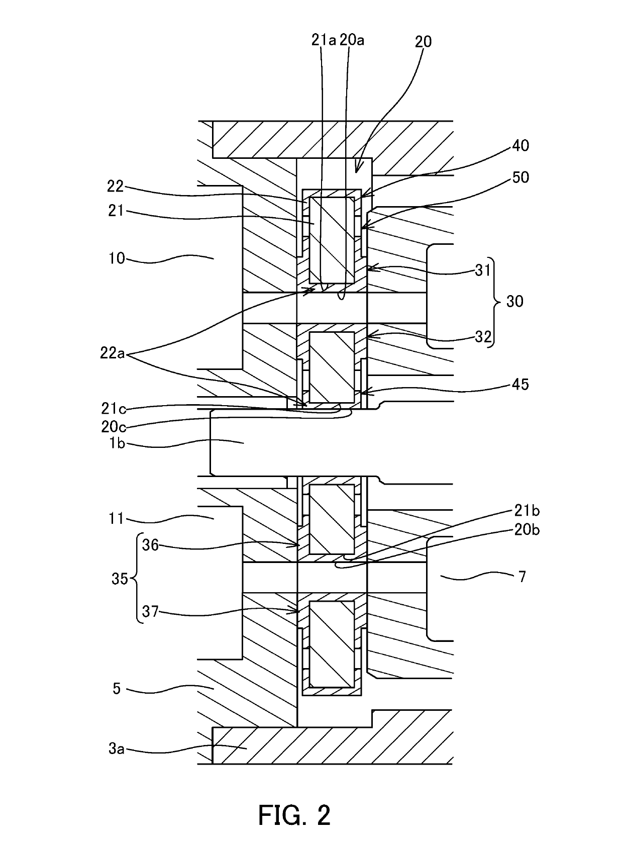
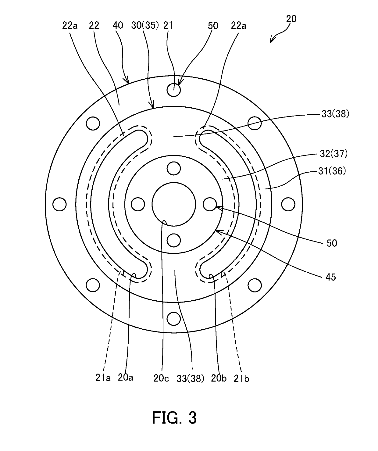
[0075]In the aforementioned first embodiment, the exposed portion 50 is provided on a part of the outer-side non-contact portion 40 and also provided on a part of the inner-side non-contact portion 45. Instead of this, a valve plate 120 of the piston pump 200 is different from the aforementioned first embodiment in a point that all of an outer-side non-contact portion 140 is formed as an exposed portion, and all of an inner-side non-contact portion 145 is formed as an exposed portion.

[0076]As illustrated in FIGS. 8 and 9, the valve plate 120 of the piston pump 200 has t...


PUM


Abstract

It includes a plurality of cylinders formed on the cylinder block; a piston slidably inserted into the cylinder; a case accommodating the cylinder block; and a valve plate formed by a core member and a resin layer coating the core member, the valve plate being interposed between the cylinder block and an end cover of the case. The valve plate has a first land portion formed by the resin layer, the first land portion being in sliding contact with the cylinder block; and an outer-side non-contact portion provided closer to an outer side in a radial direction than the first land portion, the outer-side non-contact portion being separated away from the cylinder block. At least a part of the outer-side non-contact portion is an exposed portion where the core member is exposed.

Description

TECHNICAL FIELD[0001]The present invention relates to a hydraulic rotary machine and a valve plate thereof.BACKGROUND ART[0002]JP1997-14125A discloses a swash-plate axial piston type pump including a cylinder block rotated by driving of a shaft through a spline, a piston inserted into a cylinder provided in the cylinder block in a freely reciprocating manner, a slipper provided on a base end of the piston, and a thrust plate having an inclined surface on which the slipper slides.[0003]In the axial piston pump disclosed in JP1997-14125A, the cylinder block and the valve plate slide, and the piston reciprocates while rotating and thus, an operating liquid is suctioned into the cylinder through a suction port and the valve plate and compressed and is ejected via the valve plate and an ejection port.SUMMARY OF INVENTION[0004]In some hydraulic rotary machines, a surface of a sliding member is coated with a resin layer in order to reduce sliding resistance of the member sliding in an oper...

Claims


Application Information

Patent Timeline
IPC IPC(8): F04B1/20F04B1/12F04B1/24F04B1/30F01B3/00
CPCF04B1/2021F04B1/122F04B1/2078F04B1/24F04B1/306F01B3/0076F04B1/20F03C1/0636F03C1/0647F04B1/22
Inventor ISHIKAWA, RYUNOSUKE
Owner KYB CORP
Why Eureka
Try Eureka