

Medical guidewire
- Summary
- Abstract
- Description
- Claims
- Application Information
AI Technical Summary
Benefits of technology
Problems solved by technology
Method used
Image

Examples
first embodiment
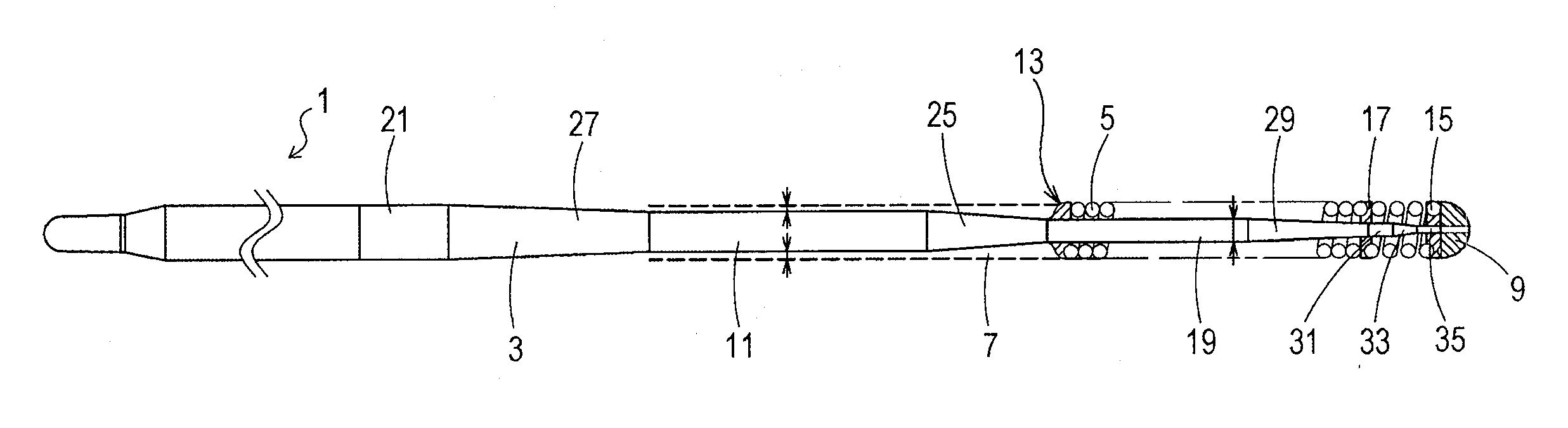
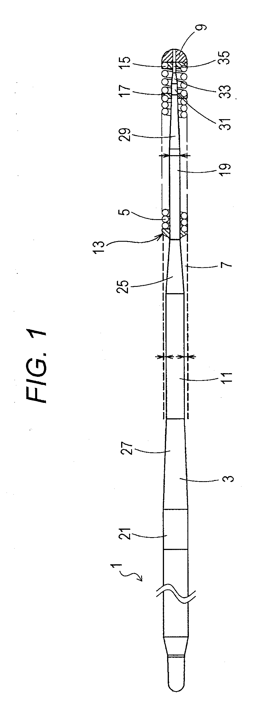
[0037]FIG. 1 illustrates an overall view of a medical guidewire according to a first embodiment of the present invention.
[0038]It is to be noted that in FIG. 1, a description is given with the left side defined as a “proximal end”, and the right side defined as a “tip” for convenience of description.
[0039]Further, in FIG. 1, the medical guidewire is reduced in length direction, and illustrated in an overall schematic manner for the sake of easy understanding. An overall size illustrated in FIG. 1 is thus different from an actual size.
[0040]In FIG. 1, a medical guidewire 1 is made up of a core shaft 3 and a coiled body 5 that covers a tip portion of the core shaft 3. The tip portion of the core shaft 3 and a tip portion of the coiled body 5 are fixed to each other at an extreme tip portion 9.
[0041]A material for the core shaft 3 is not particularly limited. In the present embodiment, stainless steel (SUS304) is used as the material for the core shaft 3. Other than that, a material su...
second embodiment
[0090]Next, a second embodiment of the medical guidewire of the present invention will be described.
[0091]FIG. 4 illustrates a partially enlarged view of the state of connection between a core shaft and a coiled body in the second embodiment.
[0092]In FIG. 4, the coil-base-end brazed portion 13 is made of a brazing material in streamlined shape which is formed in the area from the proximal end portion of the coiled body 5 to the second taper part 25. The hydrophilic material 7 is applied with a uniform thickness onto the range from the coiled body 5 to the coil-base-end brazed portion 13 and the second taper part 25.
[0093]In this case, it is possible to easily form the streamlined shape by cutting the brazing material. It is thus possible to easily manufacture a medical guidewire reduced in sliding resistance.
[0094]Also by means of this medical guidewire 1 of the second embodiment, it is possible to reduce the sliding resistance of the medical guidewire 1 at the time of pulling the m...
third embodiment
[0099]Next, a third embodiment of the medical guidewire of the present invention will be described.
[0100]FIG. 5 illustrates a partially enlarged view of the state of connection between a core shaft and a coiled body in the third embodiment.
[0101]In the third embodiment, as illustrated in FIG. 5, the hydrophilic material 7 is applied so as to form a cylindrical shape (or linear shape) in a middle area from the proximal end portion of the coiled body 5 to the second cylindrical part 11. Further, the hydrophilic material 7 is applied so as to form a curved shape in a connecting section between this middle area and the proximal end portion of the coiled body 5, and applied so as to form a curved shape in a connecting section between the middle area and the second cylindrical part. It is thus possible to further reduce the sliding resistance of the medical guidewire 1 at the time of pulling the medical guidewire 1 inside the guiding catheter, the tubular organ or the intracorporeal tissu...
PUM
| Property | Measurement | Unit |
|---|---|---|
| Length | aaaaa | aaaaa |
| Diameter | aaaaa | aaaaa |
| Electrical resistance | aaaaa | aaaaa |
Abstract
Description
Claims
Application Information