Fuel injection device

Active Publication Date: 2019-01-24
DENSO CORP
View PDF2 Cites 1 Cited by
  • Summary
  • Abstract
  • Description
  • Claims
  • Application Information

AI Technical Summary

Benefits of technology

[0022]In a second fuel injection device of the present disclosure, at least one of the inner side wall surface or the stationary core inner wall surface is curved to project in a radially inner direction of the housing in a cross section of the at least one of the inner side wall surface or the stationary core inner wall surface taken along an imaginary plane, which includes an axis of the housing. That is, the at last one of the inner side wall surface or the stationary core inner wall surface is formed to curve in the axial direction. Therefore, the at least one of the inner side wall surface or the stationary core inner wall surface can make a line contact with the flange outer wall surface or the outer side wall surface. Thus, even in the case where the orientation of the needle is changed to tilt the axis of the needle at the time of reciprocating the needle, it is possible to limit an increase in a slide resistance between each corresponding adjacent two of the flange, the gap forming member and the stationary core, and it is also possible to limit uneven wearing of the corresponding slide surfaces of the flange, the gap forming member and/or the stationary core. In this way, it is possible to limit the deterioration of the response of the needle, and it is possible to limit the unstable reciprocation of the needle in the axial direction. Thus, it is possible to limit variations in the injection amount of fuel, which is injected from the fuel injection device. Furthermore, it is possible to limit generation of wear debris. Thus, it is possible to limit the operational failure that is caused by clamping of the wear debris between members, which make relative movement therebetween.
[0023]Furthermore, in the second fuel injection device, similar to the first fuel injection device, at least one of the flange or the gap forming member can be constructed such that outer peripheral edge corners of axial end parts of the at least one of the flange or the gap forming member do not slide relative to the inner side wall surface of the gap forming member or the stationary core inner wall surface of the stationary core. In this way, it is possible to limit the operational failure of the needle.
[0024]In a third fuel injection device of the present disclosure, the flange outer wall surface is curved to project in a radially outer direction of the housing in a cross section of the flange outer wall surface taken along an imaginary plane, which includes an axis of the housing. The stationary core inner wall surface is curved to project in a radially inner direction of the housing in a cross section of the stationary core inner wall surface taken along the imaginary plane. That is, each of the flange outer wall surface and the stationary core inner wall surface is curved in the axial direction. Therefore, the flange outer wall surface and the stationary core inner wall surface can make a line contact with the inner side wall surface or the outer side wall surface. Thus, even in the case where the orientation of the needle is changed to tilt the axis of the needle at the time of reciprocating the needle, it is possible to limit an increase in a slide resistance between each corresponding adjacent two of the flange, the gap forming member and the stationary core, and it is also possible to limit uneven wearing of the slide surfaces of the flange, the gap forming member and the stationary core. In this way, it is possible to limit the deterioration of the response of the needle, and it is possible to limit the unstable reciprocation of the nee

Problems solved by technology

Therefore, in a case where the orientation of the needle is changed to tilt the axis of the needle at the time of reciprocating the needle, a slide resistance between each corresponding adjacent two of the flange, the gap forming member and the stationary core may possibly be increased, or the slide surfaces of the flange, the gap forming member and the stationary core may possibly be unevenly worn.
In this way, response of the needle may possibly be deteriorate

Method used


Image

  • Fuel injection device
  • Fuel injection device
  • Fuel injection device

Examples


Example

First Embodiment

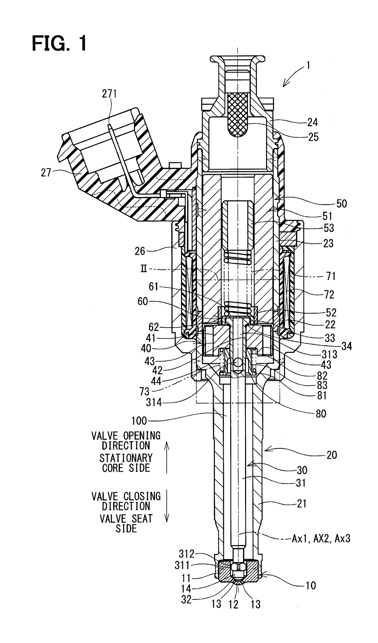
[0042]FIG. 1 shows a fuel injection device (a fuel injection valve) according to a first embodiment of the present disclosure. The fuel injection device 1 is used in, for example, an undepicted direct injection type gasoline engine (serving as an internal combustion engine) and injects gasoline as fuel in the engine.

[0043]The fuel injection device 1 includes a nozzle 10, a housing 20, a needle 30, a movable core 40, a stationary core 50, a gap forming member 60, a spring (serving as a valve seat side urging member) 71 and a coil 72.

[0044]The nozzle 10 is made of a material, such as martensitic stainless steel, which has a relatively high hardness. The nozzle 10 is quenched to have a predetermined hardness. The nozzle 10 includes a nozzle tubular portion 11 and a nozzle bottom portion 12 while the nozzle bottom portion 12 closes one end of the nozzle tubular portion 11. The nozzle bottom portion 12 has a plurality of injection holes 13, each of which connects between ...

Example

Second Embodiment

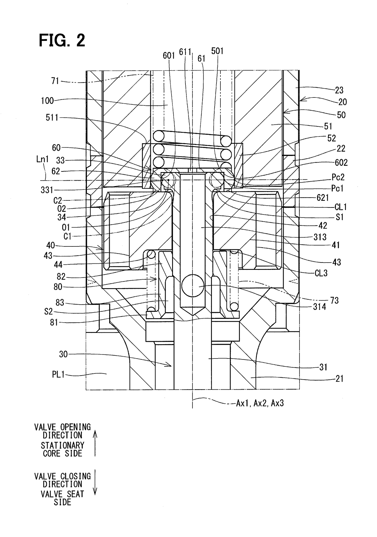
[0121]FIG. 6 shows a portion of the fuel injection device according to a second embodiment of the present disclosure. The second embodiment differs from the first embodiment with respect to the shapes of the flange 33 and the gap forming member 60.

[0122]In the second embodiment, the flange outer wall surface 331 is formed along an entire axial extent of the outer wall of the flange 33 located on the radially outer side. Furthermore, the outer side wall surface 602 is formed along an entire axial extent of the outer wall of the gap forming member 60 located on the radially outer side such that the outer side wall surface 602 is opposed to the stationary core inner wall surface 501.

[0123]The center O1 of the first imaginary circle C1 and the center O2 of the second imaginary circle C2 are located along the imaginary straight line Ln1, which is perpendicular to the axis Ax1 of the housing 20, when the plate portion 61 is in contact with the needle 30. Furthermore, the ...

Example

Third Embodiment

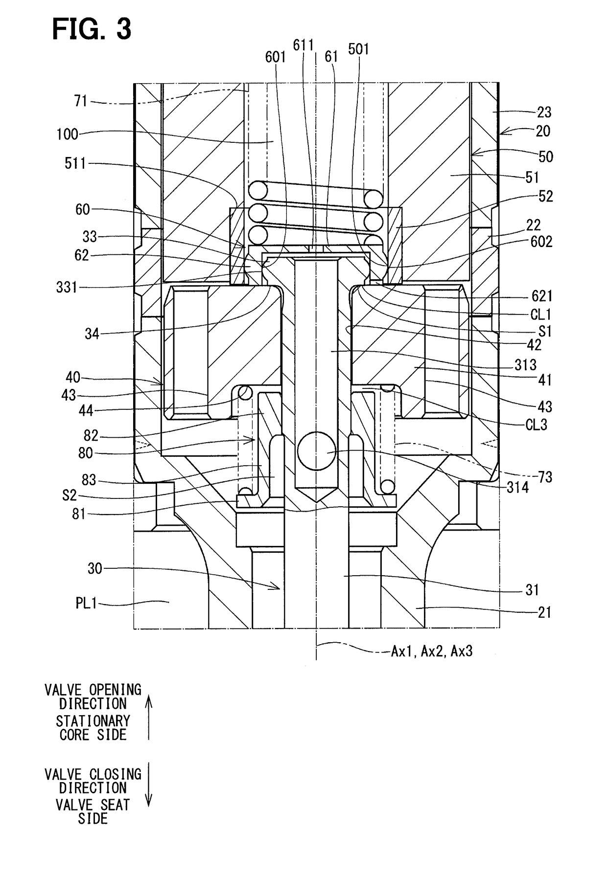
[0127]FIG. 7 shows a portion of the fuel injection device according to a third embodiment of the present disclosure. The third embodiment differs from the second embodiment with respect to the shape of the gap forming member 60.

[0128]In the third embodiment, the outer side wall surface 602 of the gap forming member 60 is formed into a cylindrical form. Furthermore, the outer diameter of the outer side wall surface 602 is set to be equal to the inner diameter of the stationary core inner wall surface 501 of the stationary core 50 or is set to be slightly smaller than the inner diameter of the stationary core inner wall surface 501. Therefore, the outer side wall surface 602 is slidable relative to the stationary core inner wall surface 501.

[0129]In the third embodiment, the rest of the structure, which is other than the above-described point, is the same as that of the second embodiment.

[0130]As discussed above, (1) in the present embodiment, the flange outer wall sur...


PUM


Abstract

An inner side wall surface of a gap forming member, which is opposed to a flange outer wall surface of a flange of a needle, is slidable relative to the flange outer wall surface. Also, an outer side wall surface of the gap forming member, which is opposed to a stationary core inner wall surface of a stationary core, is slidable relative to the stationary core inner wall surface. The flange outer wall surface and the outer side wall surface are curved to project in a radially outer direction of a housing in a cross section thereof taken along an imaginary plane, which includes an axis of the housing.

Description

CROSS REFERENCE TO RELATED APPLICATION[0001]This application is based on and incorporates herein by reference Japanese Patent Application No. 2015-172929 filed on Sep. 2, 2015.TECHNICAL FIELD[0002]The present disclosure relates to a fuel injection device that supplies fuel to an internal combustion engine.BACKGROUND ART[0003]Previously, there is known a fuel injection device that forms a gap in an axial direction between a movable core and a flange of a needle in such a manner that the movable core is accelerated in the gap and collides against the flange of the needle to implement valve opening of the needle. For example, the patent literature 1 discloses the fuel injection device that includes a gap forming member, which can form the gap in the axial direction between the movable core and the flange of the needle. In this fuel injection device, the movable core, which has an increased kinetic energy that is increased through the acceleration of the movable core in the gap, collide...

Claims


Application Information

Patent Timeline
IPC IPC(8): F02M51/06F02M61/16
CPCF02M51/0664F02M61/161F02M51/0689F02M2200/502F02M51/06F02M51/0607F02M61/18
Inventor YAMAMOTO, SHINSUKEOIKAWA, SHINOBUMATSUKAWA, TOMOJIGOTOH, MORIYASUITOH, EIJI
Owner DENSO CORP
Why Eureka
Try Eureka