Vehicle seat sliding device

Active Publication Date: 2015-01-06
AISIN SEIKI KK
View PDF19 Cites 13 Cited by
  • Summary
  • Abstract
  • Description
  • Claims
  • Application Information

AI Technical Summary

Benefits of technology

[0009]According to the above configuration, the operation member inserted into the second rail on which the cover is mounted is positioned in the lateral direction when pressed against the sliding bead. The sliding bead limits the backlash of the operation member in the lateral direction. Accordingly, while positioning the operation member in the lateral direction in a more stable state with the slid

Problems solved by technology

Therefore, although it is presently desirable that various parts be provided with multiple functions to reduce the number and weight of components, the cover is an inefficient part having only a single function.
Further, when the operation member is pivoted against the biasing force of the biasing m

Method used


Image

  • Vehicle seat sliding device
  • Vehicle seat sliding device
  • Vehicle seat sliding device

Examples


Embodiment Construction

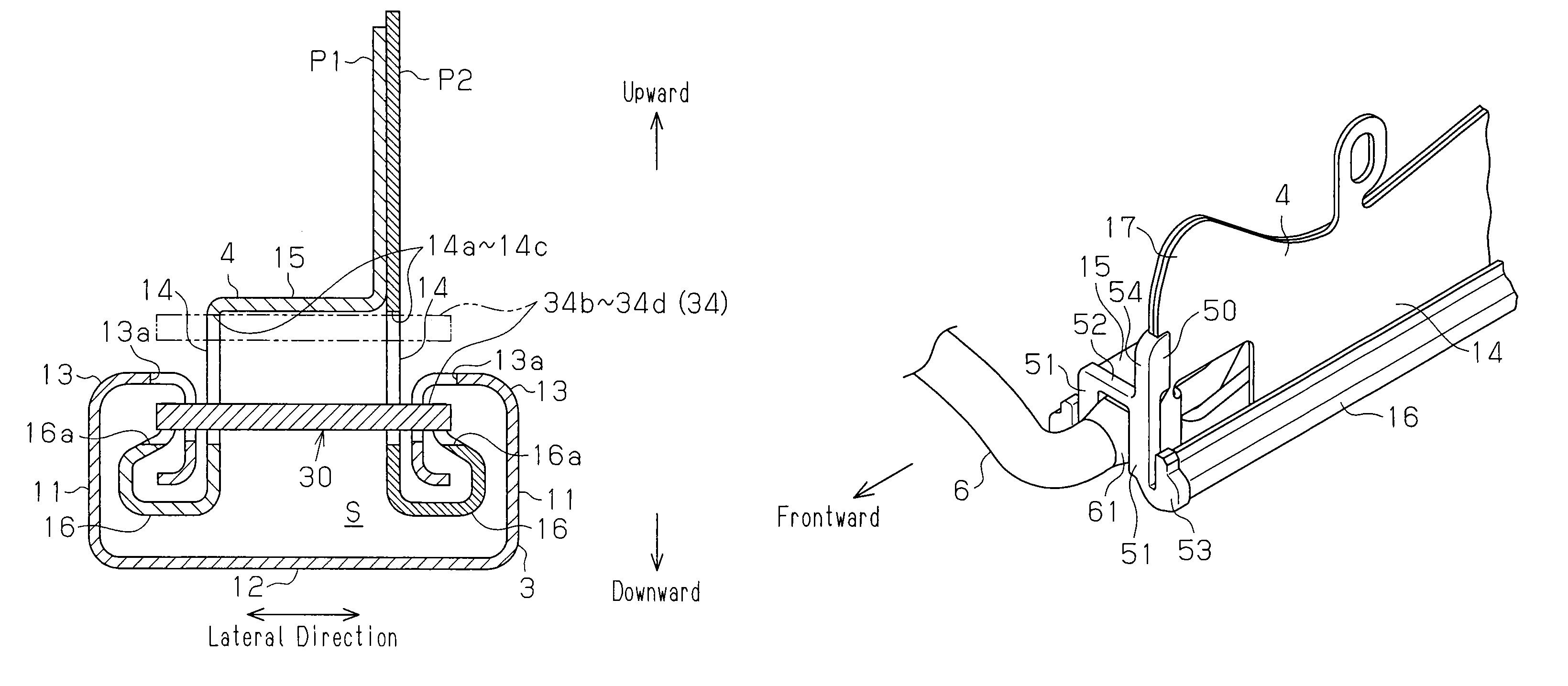
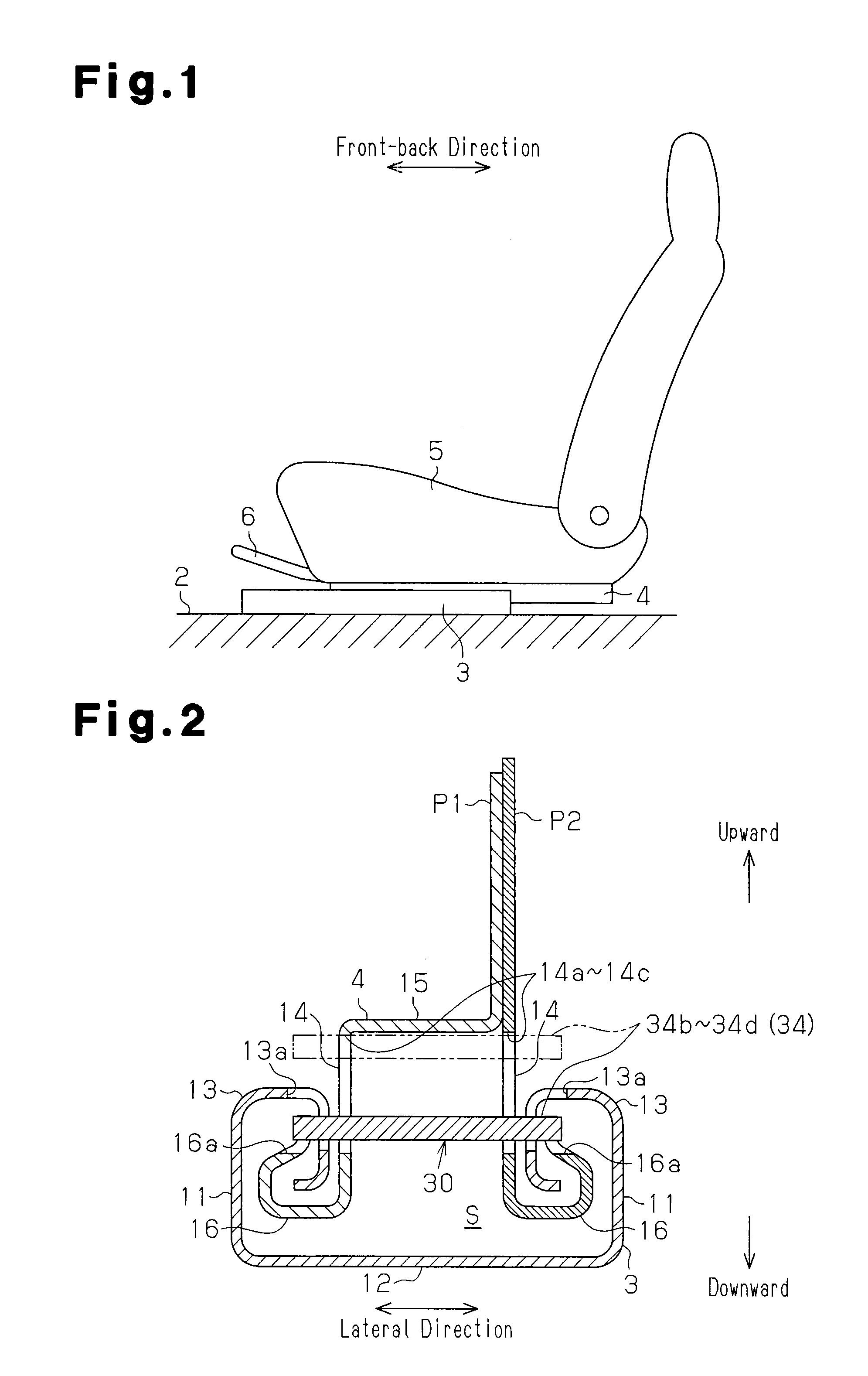
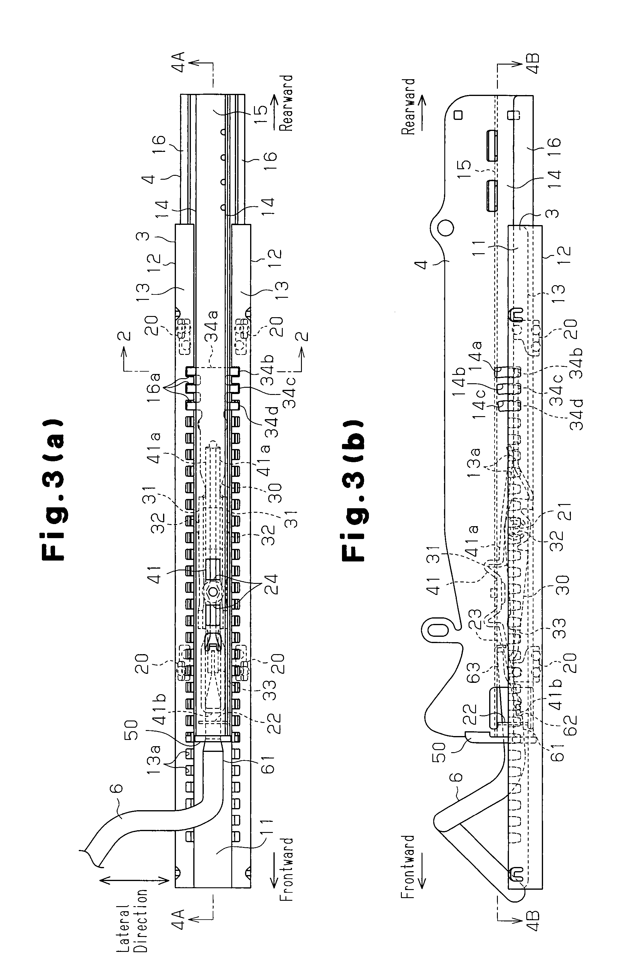
[0022]An embodiment of the present invention will now be described with reference to FIGS. 1 to 7. As shown in FIG. 1, lower rails 3, which serve as first rails, are fixed to a vehicle floor 2 such that each lower rail 3 extends in the front-back direction of a vehicle. Upper rails 4, which serve as second rails, are mounted on the corresponding lower rails 3 and movable manner relative to the corresponding lower rails 3 in the front-back direction.

[0023]FIG. 1 shows one of two paired sets of the lower rail 3 and the upper rail 4. The two paired sets are spaced apart from each other in the lateral direction of the vehicle (the direction perpendicular to the plane of FIG. 1). The left one of the paired sets facing toward the front is shown in FIG. 1. A seat 5 for seating a passenger is fixed to and supported by the upper rails 4. The movement of the upper rails 4 relative to the lower rails 3 is basically restricted. A release handle 6, which serves as an operation member, is provide...


PUM


Abstract

A vehicle seat sliding device includes: a first rail adapted to be fixed to one of a vehicle floor and a seat; a second rail adapted to be fixed to the other one of the vehicle floor and the seat, and coupled to the first rail in a relatively movable manner; an engagement member, which selectively limits and permits the relative movement of the first and the second rails; an operation member configured such that operating force to cancel the restriction of the relative movement in the second rail is transmitted to the engagement member; and a cover mounted on the first end of the second rail to close the first end. The cover has an engagement piece, which engages with a support wall provided in the second rail and restricts the pivoting of the cover when pressed against the operation member.

Description

FIELD OF THE INVENTION[0001]The present invention relates to a vehicle seat sliding device.BACKGROUND OF THE INVENTION[0002]Patent Document 1 describes an example of a known vehicle seat sliding device. Such a vehicle seat sliding device includes lower rails and upper rails, and the upper rails are coupled with the lower rails in a movable manner. A plastic cover is mounted on the upper rail, which is formed by a plate, such that the cover closes a first end located at one end of the upper rail. Direct interference between the first end and surrounding parts may be avoided by reducing exposure of the first end of the upper rail in this manner.PATENT DOCUMENTPatent Document 1[0003]Japanese Laid-Open Patent Publication No. 2010-95096SUMMARY OF THE INVENTION[0004]In the seat sliding device of Patent Document 1, the cover is mounted as an exclusive part functioning and shaped to avoid interference between the first end of the upper rail and the surrounding parts. Therefore, although it ...

Claims


Application Information

Patent Timeline
IPC IPC(8): F16M13/00B60N2/07B60N2/08
CPCB60N2/0722B60N2/0705B60N2/0715B60N2/0725B60N2/0818B60N2/085B60N2/0875
Inventor NAGURA, MIKIHITOMASUDA, SATOSHIYOSHII, MOTOHARUKIMURA, TOSHIHIROOGI, TSUNEOMIZUNO, RYOUSUKECHIBA, AKIHIRO
Owner AISIN SEIKI KK
Why Eureka
Try Eureka