Electrical discharge machine and method for manufacturing machined object using the same

Active Publication Date: 2015-09-03
DENSO CORP
View PDF3 Cites 0 Cited by
  • Summary
  • Abstract
  • Description
  • Claims
  • Application Information

AI Technical Summary

Benefits of technology

[0011]When the sliding resistance between the rail and the movement blocks becomes greater than that in a normal state, the resistance against the movement of the electrode holder in the driving direction is no longer normal. Therefore, based on an abnormality occurring in the resistance against the movement of the electrode holder in the driving direction, an operation to resolve the increase in sliding resistance is per

Problems solved by technology

However, according to experiments conducted by the inventors, problems may occur when a roller bearing is used as a member for guiding the movement of the electrode holder in a driving directi

Method used


Image

  • Electrical discharge machine and method for manufacturing machined object using the same
  • Electrical discharge machine and method for manufacturing machined object using the same
  • Electrical discharge machine and method for manufacturing machined object using the same

Examples


Example

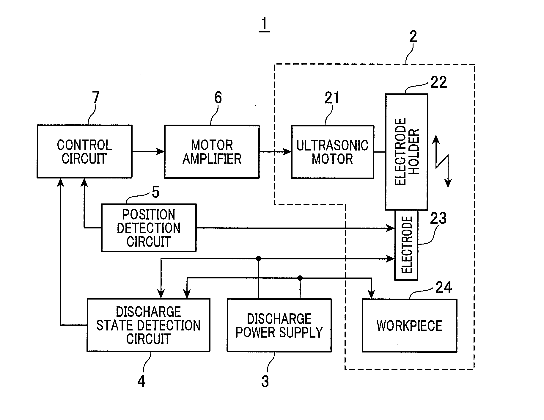
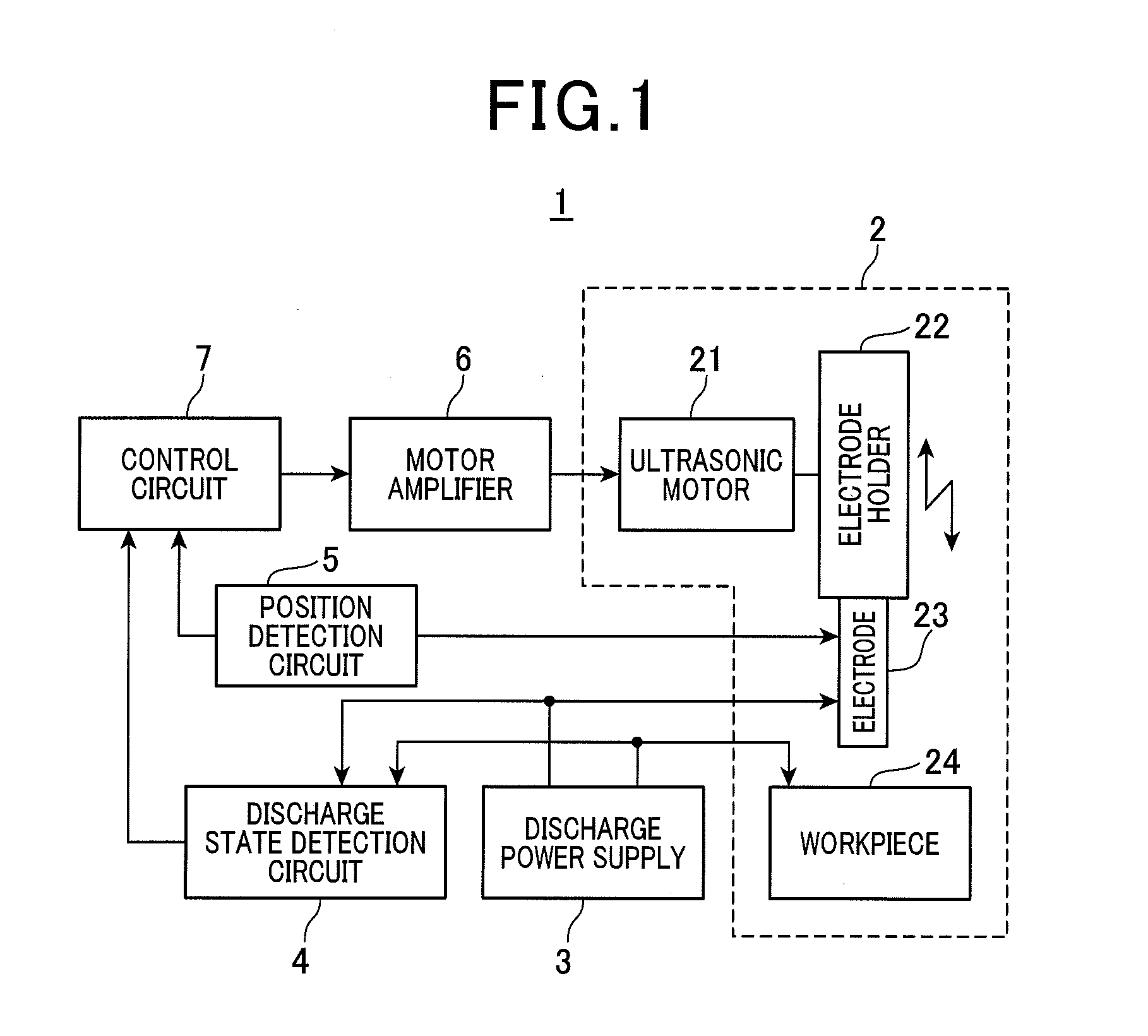
[0026]A first embodiment of the present disclosure will hereinafter be described. An electrical discharge machine 1 (see FIG. 1) according to the present embodiment is an apparatus that generates an electrical discharge by applying a voltage between an electrode and a workpiece (an object to be machined). The workpiece is melted by the electrical discharge and thereby machined

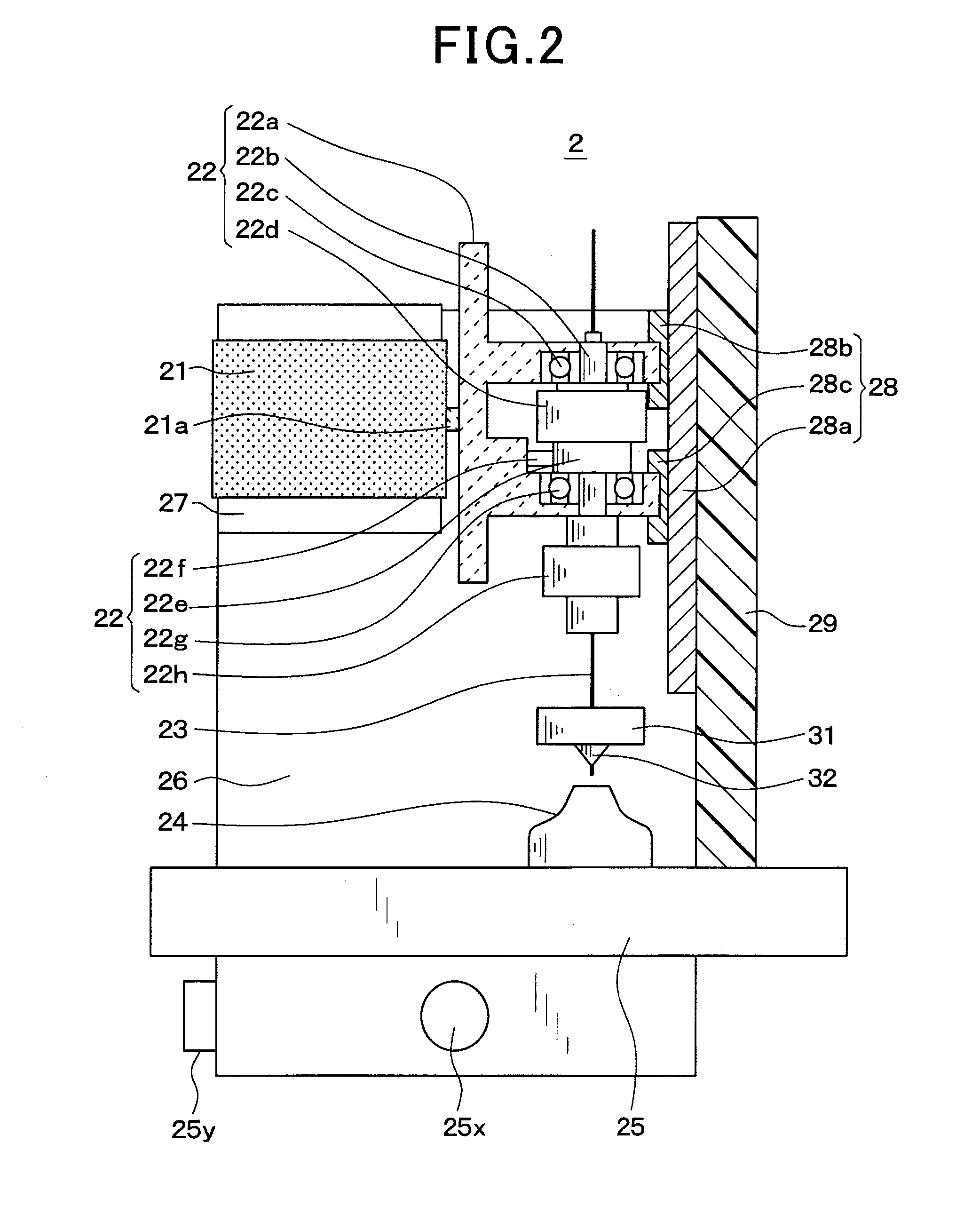
[0027]As shown in FIG. 1, the electrical discharge machine 1 includes a mechanical unit 2, a discharge power supply 3, a discharge state detection circuit 4, a position detection circuit 5, a motor amplifier 6, and a control circuit 7. The mechanical unit 2 is a section within the electrical discharge machine 1 that performs mechanical operations. The mechanical unit 2 includes an ultrasonic motor 21, an electrode holder 22, an electrode 23, and the like. A workpiece 24 is set on the mechanical unit 2.

[0028]The ultrasonic motor 21 moves the electrode holder 22 in a driving direction (specifically, an up / down di...

Example

Second Embodiment

[0170]Next, a second embodiment of the present disclosure will be described. According to the present embodiment, the content of the guide abnormality determination process performed by the control circuit 7 at step S180 in FIG. 7 is changed from that according to the first embodiment. The guide abnormality determination process is changed from the process in FIG. 11 to the process in FIG. 13.

[0171]In the process in FIG. 13, steps S205 and 5210 from the process in FIG. 11 have been replaced with step S208. At step S208, the control circuit 7 determines whether or not the absolute value of the difference between the descent speed Vd (positive value) measured at the most recent step S113 and the ascent speed Vu (positive value) measured at the most recent step S175 is greater than a predetermined reference speed difference VT.

[0172]When determined that the absolute value is greater than the reference speed difference VT, the control circuit 7 proceeds to step S225 and...


PUM

PropertyMeasurementUnit
Electrical resistanceaaaaaaaaaa
Speedaaaaaaaaaa

Abstract

In an electrical discharge machine that applies a voltage between an electrode and a workpiece to generate electrical discharge, an electrode holder holds the electrode. An ultrasonic motor has a fingertip that comes into contact with electrode holder, and moves electrode holder in a driving direction by moving the fingertip in an annular manner at an ultrasonic-range frequency. A roller bearing guides the movement of the electrode holder in the driving direction. A control circuit controls a position of the electrode in the driving direction by driving the ultrasonic motor, and moves the electrode holder based on an abnormality occurring in resistance against the movement of the electrode holder in the driving direction such that the electrode holder is moved by a movement distance equivalent to when the largest roller element among a plurality of roller elements of the roller bearing rolls and rotates once without sliding or longer.

Description

CROSS-REFERENCE TO RELATED APPLICATION[0001]This application is based on and claims the benefit of priority from Japanese Patent Application No. 2014-038288, filed Feb. 28, 2014, the disclosure of which is incorporated herein in its entirety by reference.BACKGROUND[0002]1. Technical Field[0003]The present invention relates to an electrical discharge machine and a method for manufacturing a machined object using the electrical discharge machine.[0004]2. Related Art[0005]An ultrasonic motor is conventionally known (refer to, for example, JP-A-2011-104735). The ultrasonic motor is used in an electrical discharge machine to move an electrode holder that holds an electrode. The ultrasonic motor has a fingertip that comes into contact with the electrode holder. The ultrasonic motor drives the electrode holder by moving the fingertip in an annular manner at an ultrasonic-range frequency.[0006]When an ultrasonic motor such as this is used, the movement of the electrode holder can be control...

Claims


Application Information

Patent Timeline
IPC IPC(8): B23H1/04
CPCB23H1/04B23H1/00B23H7/30B23H7/38B23H9/14B23H11/00
Inventor YASUDA, KOUICHIROUINOBE, YASUJIITOH, AKIRANAGAI, NOBUHIKOYAMAGUCHI, TETSUJIOOTANI, HIROYUKI
Owner DENSO CORP
Why Eureka
Try Eureka