Coating device

A coating device and coating technology are applied in the direction of devices and coatings for coating liquid on the surface, which can solve the problems of difficulty in uniformly controlling the thickness of the coating and increased friction.

Inactive Publication Date: 2003-04-23
菱技精密工具株式会社
View PDF0 Cites 1 Cited by
  • Summary
  • Abstract
  • Description
  • Claims
  • Application Information

AI Technical Summary

Problems solved by technology

Then, the frictional force generated by the coating agent increases,...

Method used


Image

  • Coating device
  • Coating device
  • Coating device

Examples


Embodiment Construction

[0027] Embodiments of the coating apparatus of the present invention are described below with reference to the drawings. Although the present invention relates to a coating apparatus for uniformly coating the surface of flexible belt supports such as films and sheets running in one direction with a coating agent to form a thin coating, the specific structural and operational details disclosed herein are representative only. nature and do not limit the scope of the present invention.

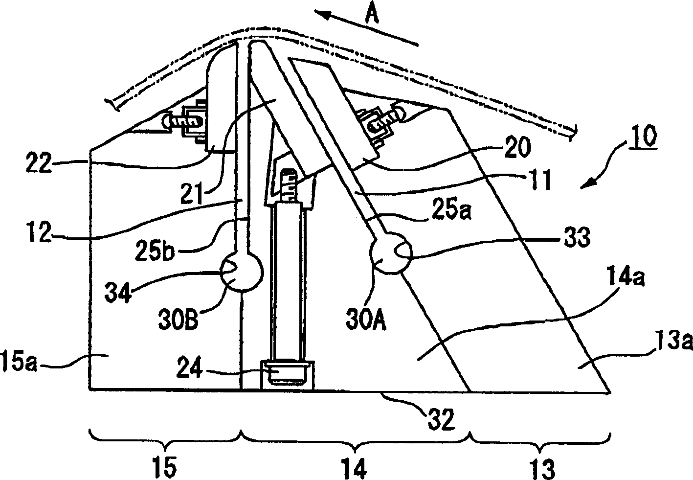
[0028] An embodiment of the coating device of the present invention is in figure 1 shown in . exist figure 1 , the coating device has a coating head 10 . In the coating head 10 , the first groove 11 is located between the first edge unit 13 and the second edge unit 14 , and the second groove 12 is located between the second edge unit 14 and the third edge unit 15 . The first, second and third edge units 13, 14 and 15 are arranged in this order in the running direction of the flexible belt s...


PUM


Abstract

In order to provide a coating apparatus in which an edge can be fixed rigidly so as to apply a coating agent at a uniform thickness, edge units are provided which comprise edge support members (13a, 14a, 15a) and edges (20, 21, 22) which are attached to the tips of the edge support members so as to slide on a flexible tape support member (23). The edge (21) which is not disposed at both ends in the running direction of the flexible tape support member is fixed to the edge support member (14a) by an edge fixing member (24) which is inserted in a direction from a bottom portion of the coating apparatus toward the edge (21). The edge (21) is fixed so as to be pulled into a recessed section (30) formed on the edge support member (14a) by the edge fixing member (24).

Description

technical field [0001] The present invention relates to a coating device for applying a thin layer of coating agent to a running flexible belt support. In particular, the invention relates to applicator heads for discharging coating agent. Background technique [0002] As for a coating head for forming a thin coating layer, generally known is, for example, a structure disclosed in Japanese Unexamined Patent Application, First Publication No. Sho62-241574 (hereinafter referred to as first prior art). Such as Figure 5 As shown, the applicator head 5 has two parallel parts 1 , 2 . Between the two parallel pieces 1 , 2 a groove 3 is formed. Adjusting pieces 4 , 4 are arranged at both longitudinal ends of the slot 3 , which are used to adjust the width of the slot 3 . [0003] In the coating head 5 having this structure, when the long wide flexible belt support 6 runs on the top end of the parallel edge member in the direction shown by the arrow A in the figure, it is dischar...

Claims


Application Information

Patent Timeline
IPC IPC(8): B05C5/02B05C9/06
CPCB05C9/06B05C5/0254B05C5/02
Inventor 福田努金山利彦
Owner 菱技精密工具株式会社
Why Eureka
Try Eureka