Method and system for MIMO transmission in a distributed transceiver network

Active Publication Date: 2013-04-18
GOLBA LLC
View PDF3 Cites 62 Cited by
  • Summary
  • Abstract
  • Description
  • Claims
  • Application Information

AI Technical Summary

Benefits of technology

[0013]A method and/or system for MIMO transmission in a distributed transceiver network, substantially as shown

Problems solved by technology

However, these higher frequencies m

Method used


Image

  • Method and system for MIMO transmission in a distributed transceiver network
  • Method and system for MIMO transmission in a distributed transceiver network
  • Method and system for MIMO transmission in a distributed transceiver network

Examples


Embodiment Construction

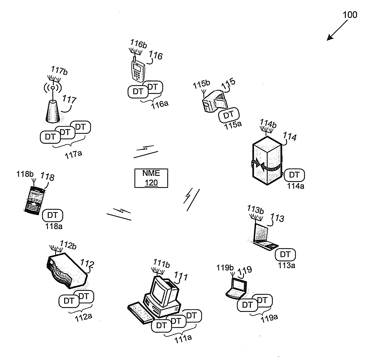
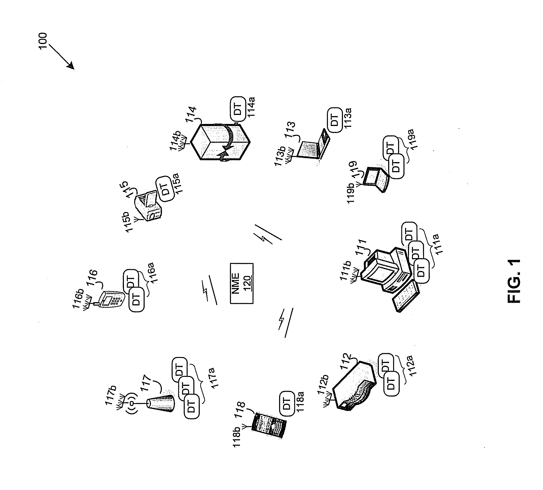
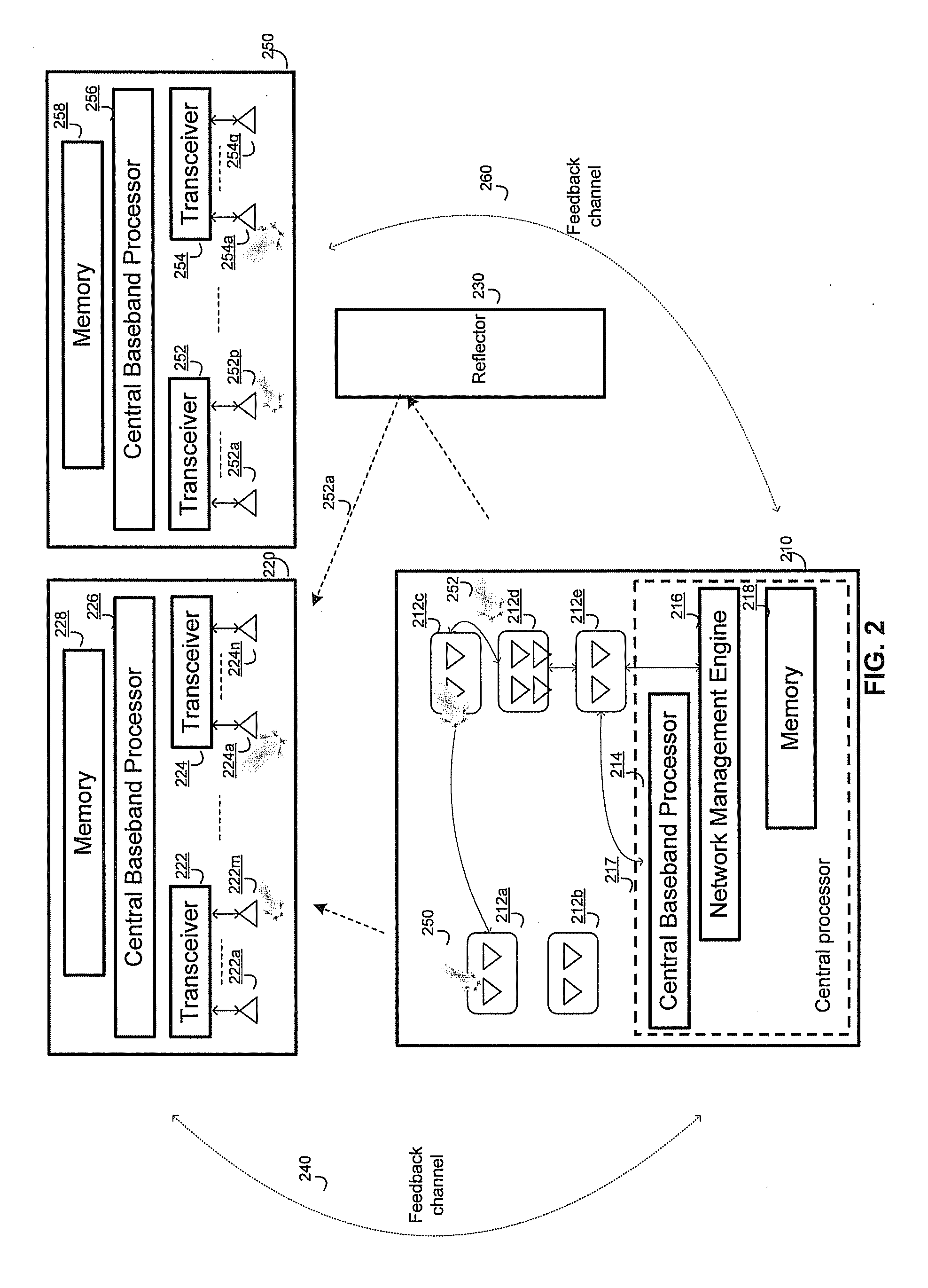
[0022]Certain embodiments of the invention may be found in a method and system for Multi-Input Multi-Output (MIMO) transmission in a distributed transceiver network. In accordance with various exemplary embodiments of the invention, a transmitting device in a network comprises a plurality of distributed transceivers, a central baseband processor and a network management engine. The central baseband processor may generate data streams at baseband. Diversity coding such as, for example, space-time coding, space-time-frequency coding, orthogonal space-time coding, spatial multiplexing, or multi-user MIMO (MU-MIMO) coding may be performed over the generated data streams at baseband. The transmitting device may concurrently transmit each of the coded streams in a same radio frequency (RF) band to a receiving device over the distributed transceivers through associated antennas. The coded data streams in the baseband may be initially converted into different corresponding intermediate freq...


PUM


Abstract

A transmitting device comprises a plurality of distributed transceivers, a baseband processor and a network management engine. Data streams are generated at baseband by the baseband processor. Diversity coding such as space-time coding may be performed over the generated data streams in the baseband. The transmitting device concurrently transmits each of the coded streams in a same radio frequency (RF) band to a receiving device over the entire distributed transceivers through associated antennas. When needed, the network management engine may identify one or more auxiliary devices providing available transceivers and antenna beamformers to the transmitting device for sharing. Beam patterns and antenna orientations may be determined for associated antennas of the available transceivers for the transmitting device. Each of the coded data streams in the same radio frequency band may be transmitted to the receiving device over the entire available transceivers for the transmitting device through the associated antennas.

Description

CROSS-REFERENCE TO RELATED APPLICATIONS / INCORPORATION BY REFERENCE[0001]This patent application makes reference to, claims priority to and claims benefit from U.S. Provisional Patent Application Ser. No. 61 / 548,201 filed on Oct. 17, 2011.[0002]This application makes reference to:[0003]U.S. application Ser. No. ______ (Attorney Docket No. 25066US02) filed on May 16, 2012;[0004]U.S. application Ser. No. ______ (Attorney Docket No. 25067US02) filed on May 16, 2012;[0005]U.S. application Ser. No. ______ (Attorney Docket No. 25068US02) filed on May 16, 2012;[0006]U.S. application Ser. No. ______ (Attorney Docket No. 25069US02) filed on May 16, 2012;[0007]U.S. application Ser. No. ______ (Attorney Docket No. 25070US02) filed on May 16, 2012; and[0008]U.S. application Ser. No. ______ (Attorney Docket No. 25072US02) filed on May 16, 2012.[0009]Each of the above stated applications is hereby incorporated herein by reference in its entirety.FIELD OF THE INVENTION[0010]Certain embodiments of t...

Claims


Application Information

Patent Timeline
IPC IPC(8): H04L27/00H04B1/38H04W4/80
CPCH04W88/06H04W88/02H04B7/0689H04W84/12H04L5/0032H04W4/008Y02B60/50H04W4/80H04B1/401Y02D30/70H04W72/51H04W72/54H04B7/0408H04B7/043H04B1/40H04L27/12H04W72/542H04B7/0413H04B7/0897H04W24/08H04W72/0453H04W72/046H04W72/0473H04B7/024
Inventor MOSHFEGHI, MEHRAN
Owner GOLBA LLC
Why Eureka
Try Eureka