Tennis swing analysis method

a tennis swing and analysis method technology, applied in the field of tennis swing analysis, can solve the problems of large size, complicated, and inconvenient fitting of measuring equipment in tennis clubhouses, and achieve the effect of accurate analysis of swings

Active Publication Date: 2013-04-18
SUMITOMO RUBBER IND LTD
View PDF3 Cites 28 Cited by
  • Summary
  • Abstract
  • Description
  • Claims
  • Application Information

AI Technical Summary

Benefits of technology

[0013]An object of the present invention is to provide an apparatus which can acc

Problems solved by technology

Meanwhile, when a player attempts to control the speed of a ball in hitting the ball with a racket having an excessively high resilience coefficient, the player loosens their h

Method used


Image

  • Tennis swing analysis method
  • Tennis swing analysis method
  • Tennis swing analysis method

Examples


Embodiment Construction

[0046]The following will describe in detail the present invention, based on preferred embodiments with reference to the accompanying drawings.

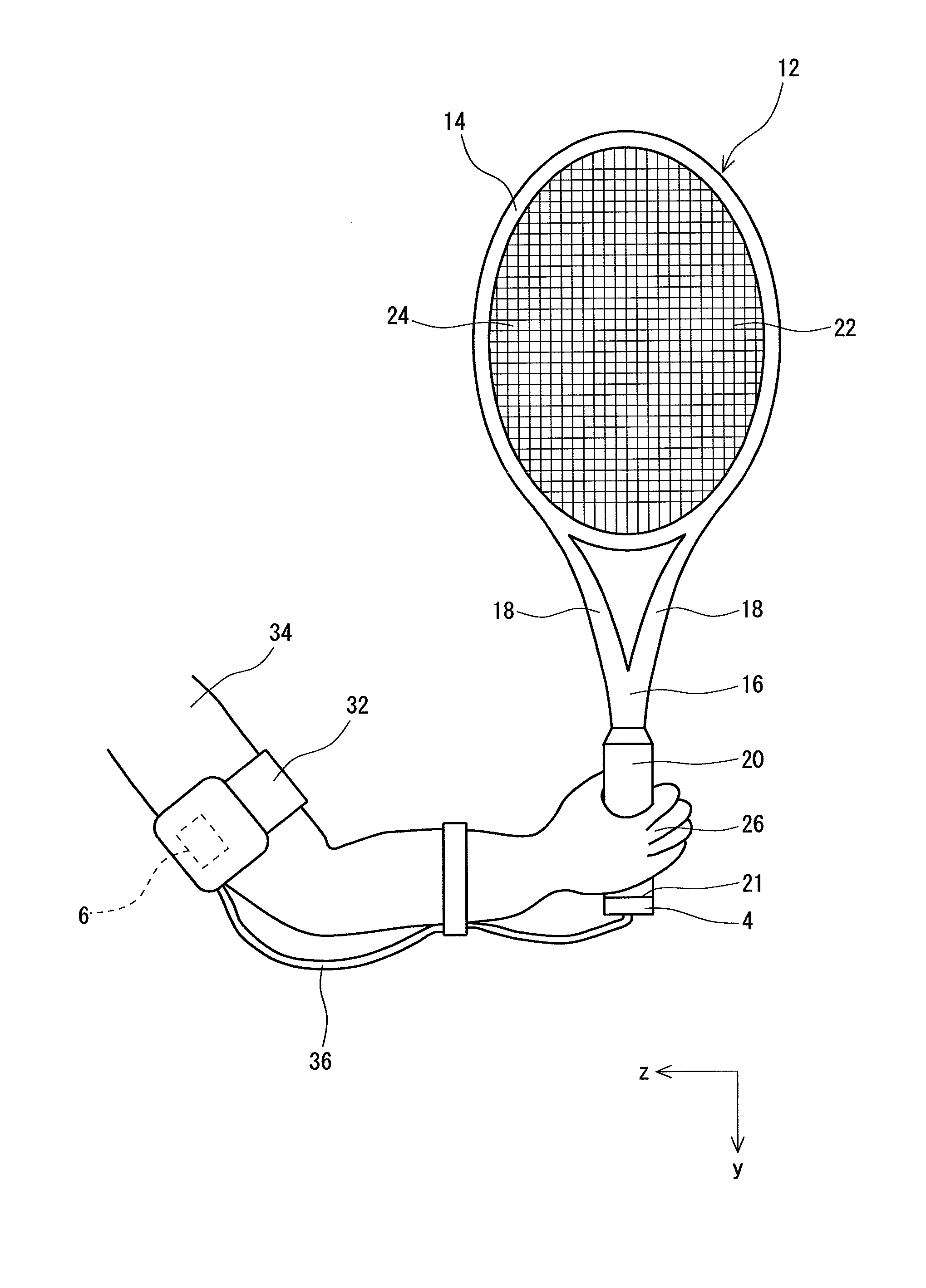
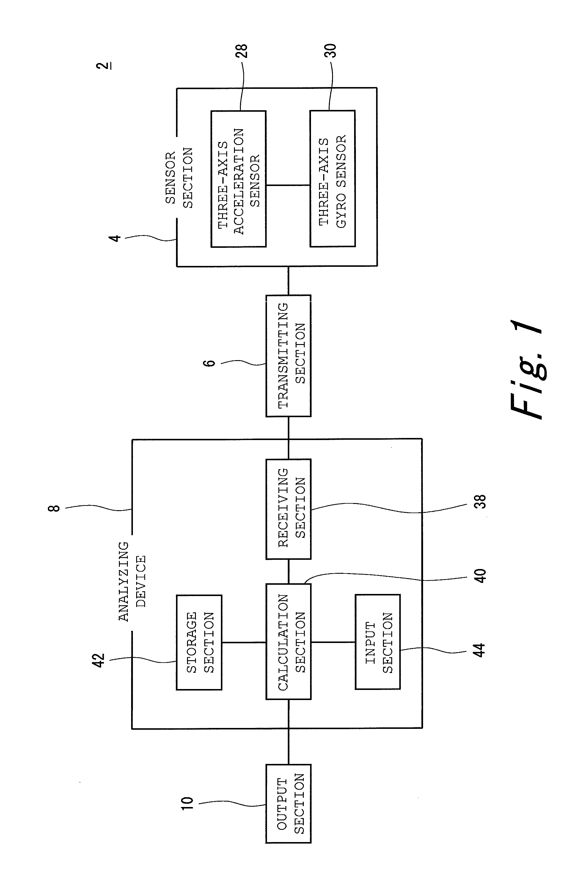
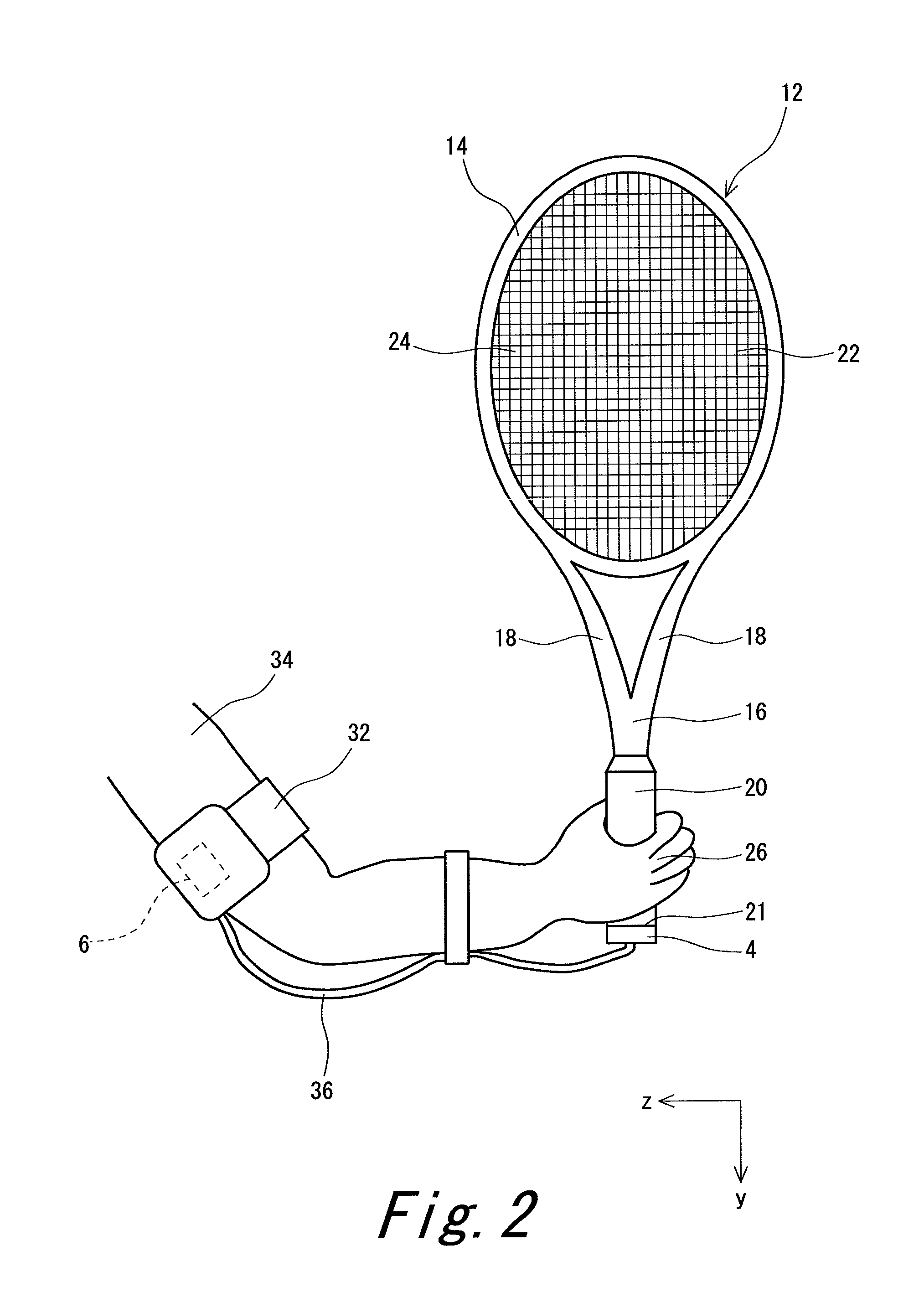
[0047]A tennis swing analyzing apparatus 2 shown in FIGS. 1 and 2 includes a sensor section 4, a transmitting section 6, an analyzing device 8, and an output section 10. FIG. 2 shows a portion of the analyzing apparatus 2 with a tennis racket 12. The tennis racket 12 includes a head 14, a shaft 16, a pair of throats 18 extending from the head 14 to the shaft 16, and a grip 20 connected to the shaft 16. The racket 12 also includes a gut 22 stretched laterally and longitudinally on the head 14. By the gut 22, a face 24 is formed.

[0048]In FIG. 2, the grip 20 is held with the right hand 26 of a player. As shown in FIG. 2, the longitudinal direction of the shaft 16 coincides with the direction of a y-axis. The direction of the y-axis is parallel to the face 24. The direction from the head 14 toward the grip 20 is the positive direction of the y-axi...


PUM


Abstract

A swing analyzing apparatus 2 includes:
a three-axis acceleration sensor 28 attached to a tennis racket, for measuring accelerations in the directions of three axes when a swing for hitting a tennis ball is taken with the tennis racket;
a three-axis gyro sensor 30 attached to the tennis racket, for measuring angular speeds about the three axes; and
an analyzing device 8. The analyzing device 8 has a receiving function to receive data regarding the accelerations and the angular speeds from the three-axis acceleration sensor 28 and the three-axis gyro sensor 30; a coordinate axis conversion function to convert relative coordinate axes that are the three axes for the accelerations into absolute coordinate axes on the basis of the angular speeds; and a calculation function to calculate an index of the swing on the basis of accelerations resulting from the coordinate axis conversion.

Description

[0001]This application claims priority on Patent Application No. 2011-226495 filed in JAPAN on Oct. 14, 2011. The entire contents of this Japanese Patent Application are hereby incorporated by reference.BACKGROUND OF THE INVENTION[0002]1. Field of the Invention[0003]The present invention relates to methods for analyzing tennis swing and apparatuses used for performing the methods.[0004]2. Description of the Related Art[0005]Swing in tennis is different from player to player. Swing is influenced by the specifications of a tennis racket. For example, when a player attempts to hit a ball with a racket having a low resilience coefficient to obtain a high speed, the player tenses themselves. Meanwhile, when a player attempts to control the speed of a ball in hitting the ball with a racket having an excessively high resilience coefficient, the player loosens their hand. Matching between a player and a racket is important. Appropriate swing analysis allows for accurate fitting. Appropriate...

Claims


Application Information

Patent Timeline
IPC IPC(8): A63B69/38
CPCA63B69/38A63B49/00A63B2220/40G06V40/23
Inventor YAMAMOTO, YOSUKETAKIHARA, HIRONORIHORIUCHI, KUNIYASU
Owner SUMITOMO RUBBER IND LTD
Why Eureka
Try Eureka