Fluidized bed furnace and waste treatment method

Inactive Publication Date: 2013-04-25
KOBELCO ECO-SOLUTIONS CO LTD
View PDF7 Cites 0 Cited by
  • Summary
  • Abstract
  • Description
  • Claims
  • Application Information

AI Technical Summary

Benefits of technology

The present invention is about a fluidized bed furnace and a waste treatment method that can efficiently produce combustible gas from waste. This invention can help reduce waste and provide a sustainable solution for energy production.

Problems solved by technology

Thus, in the case where there is a fluctuation in supply of waste or a qualitative change in components of waste, it is impossible to stably generate a combustible gas.
For example, in the case where generated combustible gas is used for a gas engine to generate electric power, if a combustible gas is generated with large fluctuations, it is impossible to obtain stable energy.

Method used


Image

  • Fluidized bed furnace and waste treatment method
  • Fluidized bed furnace and waste treatment method
  • Fluidized bed furnace and waste treatment method

Examples


embodiment

Outline of Embodiment

[0072]The outline of the above embodiment is as follows.

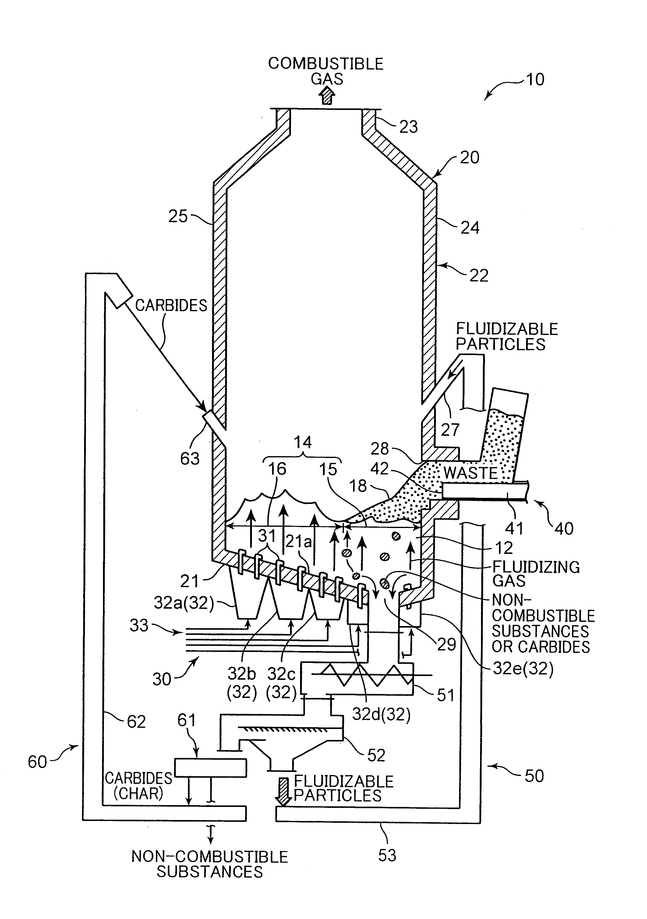
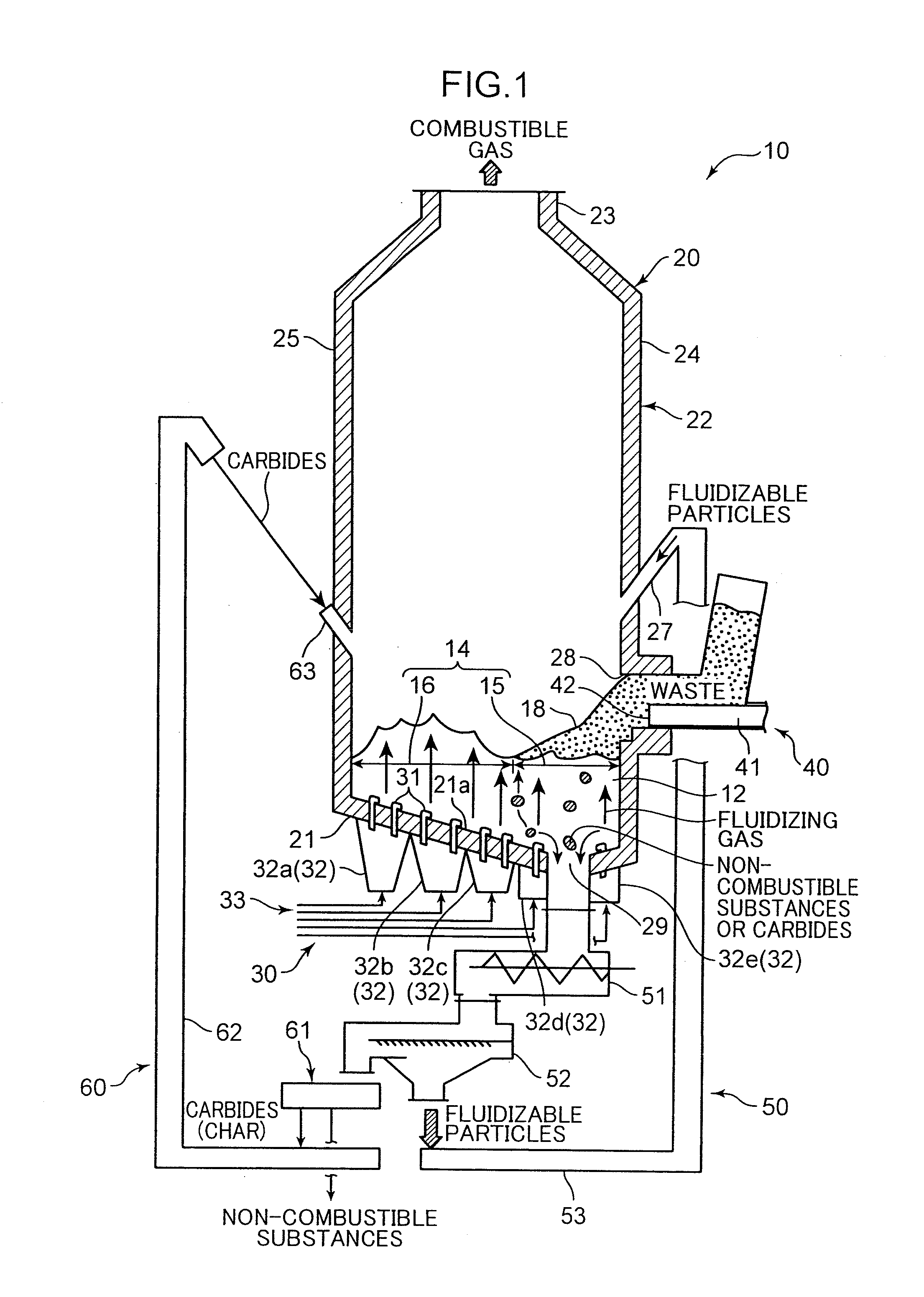
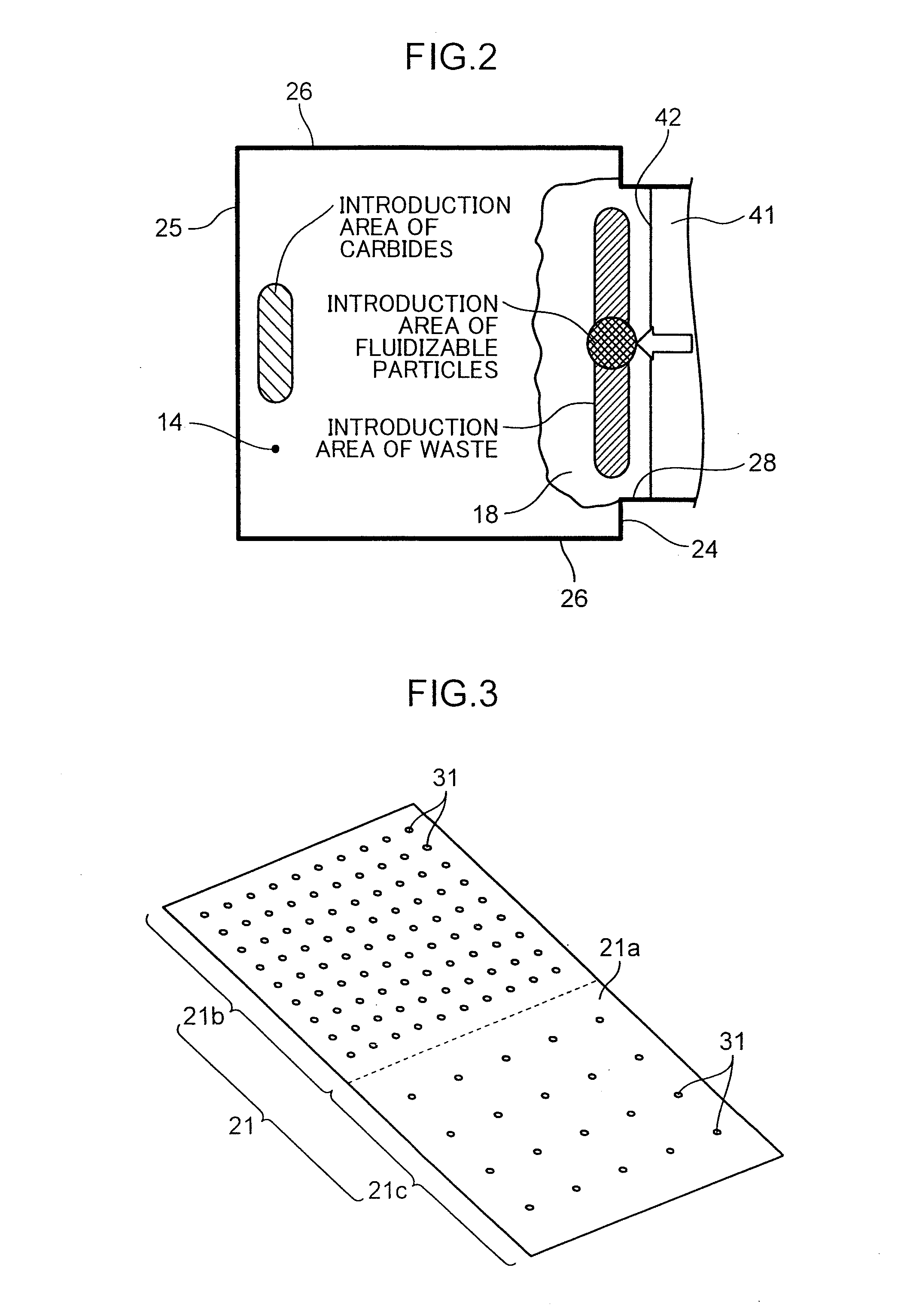
[0073]The fluidized bed furnace according to the above embodiment is designed to heat waste to extract a combustible gas from the waste. The fluidized bed furnace comprises: fluidizable particles making up a fluidized bed to heat the waste; a furnace body having a bottom wall supporting the fluidizable particles from therebelow, and a sidewall standing upwardly from the bottom wall, wherein the bottom wall has a mixture discharge port provided at a position offset from a center position of the bottom wall in a specific direction to discharge non-combustible substances in the waste and carbides produced by heating of the waste, together with a part of the fluidizable particles, and an upper surface of the bottom wall is inclined to become lower toward the mixture discharge port so as to cause the fluidizable particles to fall on the upper surface of the bottom wall toward the mixture discharge port; a gas su...


PUM


Abstract

A waste treatment technique includes: blowing a fluidizing gas from around a mixture discharge port to form a first fluidization region having a degree of fluidization of the fluidizable particles which is set to an extent allowing waste to be accumulated on fluidizable particles, while blowing a fluidizing gas between the first fluidization region and an opposite-side wall at a higher flow velocity to form a second fluid region having a degree of fluidization of fluidizable particles greater than that in the first fluidization region, whereby the fluidizable particles are mixed with the waste to gasify the waste; and supplying waste from a supply-side sidewall portion onto the fluidized bed to cause the waste to be accumulated on the first fluidization region while causing the accumulated waste to be moved into the second fluidization region step-by-step.

Description

TECHNICAL FIELD[0001]The present invention relates to a fluidized bed furnace designed to heat waste in a fluidized bed formed by fluidizing fluidizable particles to thereby extract a combustible gas from the waste, and a waste treatment method.BACKGROUND ART[0002]Heretofore, as a fluidized bed furnace, there has been known one type described in the following Patent Document 1. As illustrated in FIG. 9, this fluidized bed furnace comprises a furnace body 104 having fluidizable sand (fluidizable particles) 102 in a furnace bottom section, and an air supply section 106 for supplying air into the fluidizable sand 102 in the furnace bottom section so as to fluidize the fluidizable sand 102 to form a fluidized bed. The furnace body 104 has a sidewall. The sidewall is provided with an input section 108 for inputting waste onto the fluidized bed therefrom.[0003]In this fluidized bed furnace 100, the air supply section 106 is adapted to supply air into high-temperature fluidizable sand 102....

Claims


Application Information

Patent Timeline
IPC IPC(8): F23G5/027F23C10/10F23C10/20F23G5/30
CPCF23G5/027F23G5/30F23G5/0276F23C10/20F23C10/10F23C10/22F23C10/26F23G2205/101
Inventor KAWAI, TAKUYAHOSODA, HIROYUKIITO, TADASHI
Owner KOBELCO ECO-SOLUTIONS CO LTD
Why Eureka
Try Eureka