Ultrasonic flow rate measuring device and ultrasonic flow rate measuring method
a technology of ultrasonic flow rate and measuring device, which is applied in the direction of measurement device, volume/mass flow by dynamic fluid flow effect, instruments, etc., can solve the problems of disturbing the measurement of the proper propagating wave, the attachment and detachment of the ultrasonic flow rate measuring device with respect to the tube body is not easy
- Summary
- Abstract
- Description
- Claims
- Application Information
AI Technical Summary
Benefits of technology
Problems solved by technology
Method used
Image

Examples
embodiment 1
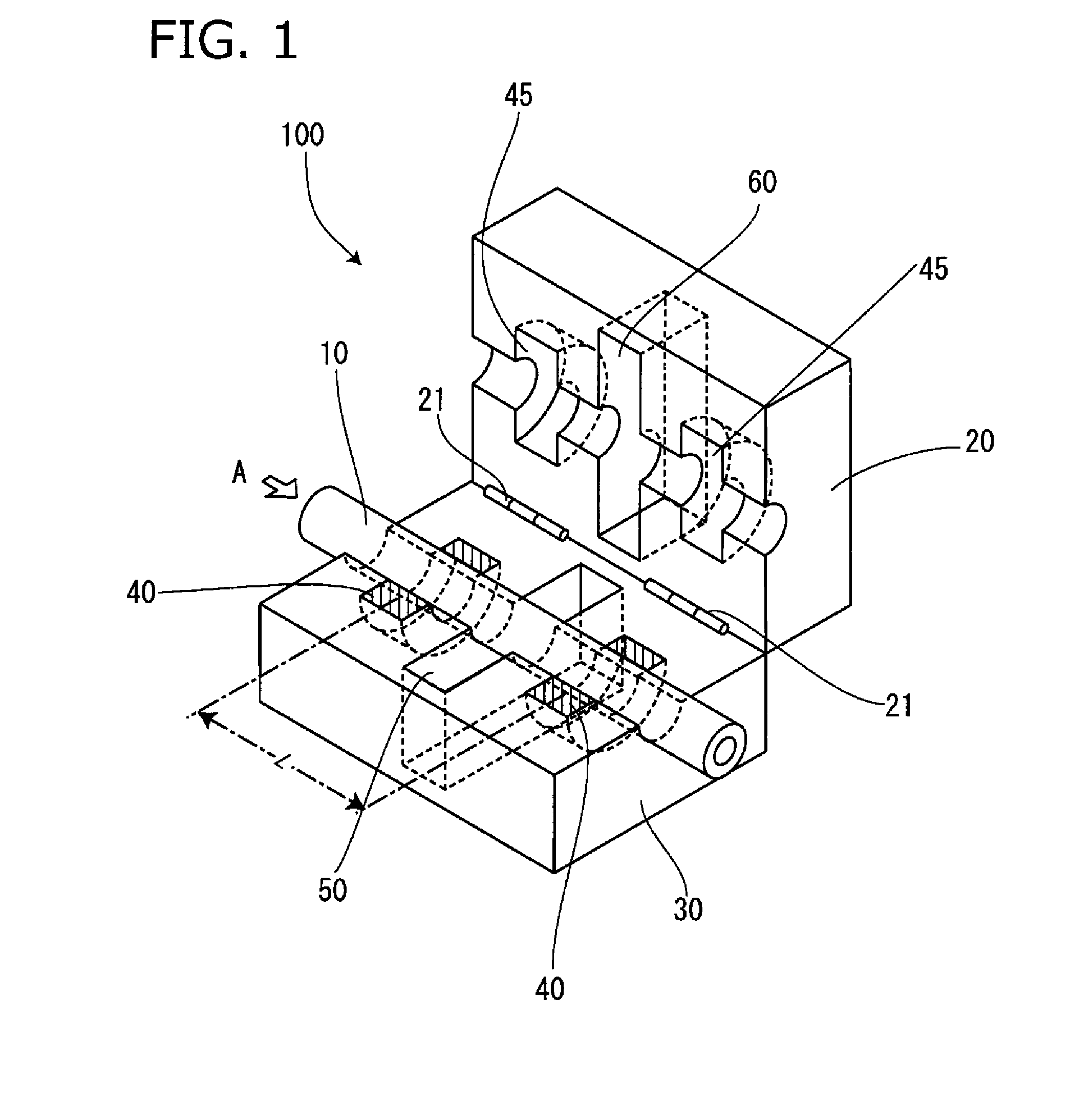
[0060]An Embodiment 1 of the present invention is an embodiment of a configuration equipped with a pair of ultrasonic transmitting-receiving means 40, and is shown in FIG. 1 and FIG. 3A. FIG. 1 is a perspective view in the case where an ultrasonic flow meter 100 of Embodiment 1 is mounted to a tube 10, and a perspective view in the state where a pair of upper and lower sensor cases 20, 30 of the ultrasonic flow meter 100 is opened. In the present specification, vertical, anteroposterior, and lateral directions are represented in the direction shown in FIG. 1. Therefore, it is a matter of design variation to arrange the same upside down, left-right reversed, and front-back reversed, when applied to a product, and is obviously included in the technical range of the present invention. Further, in the following embodiments, a cross-sectional shape of a transfer tube may be any shape such as circular, oblong, horn-shape, but will be explained in the embodiments as a tube.
[0061]The ultras...
embodiment 2
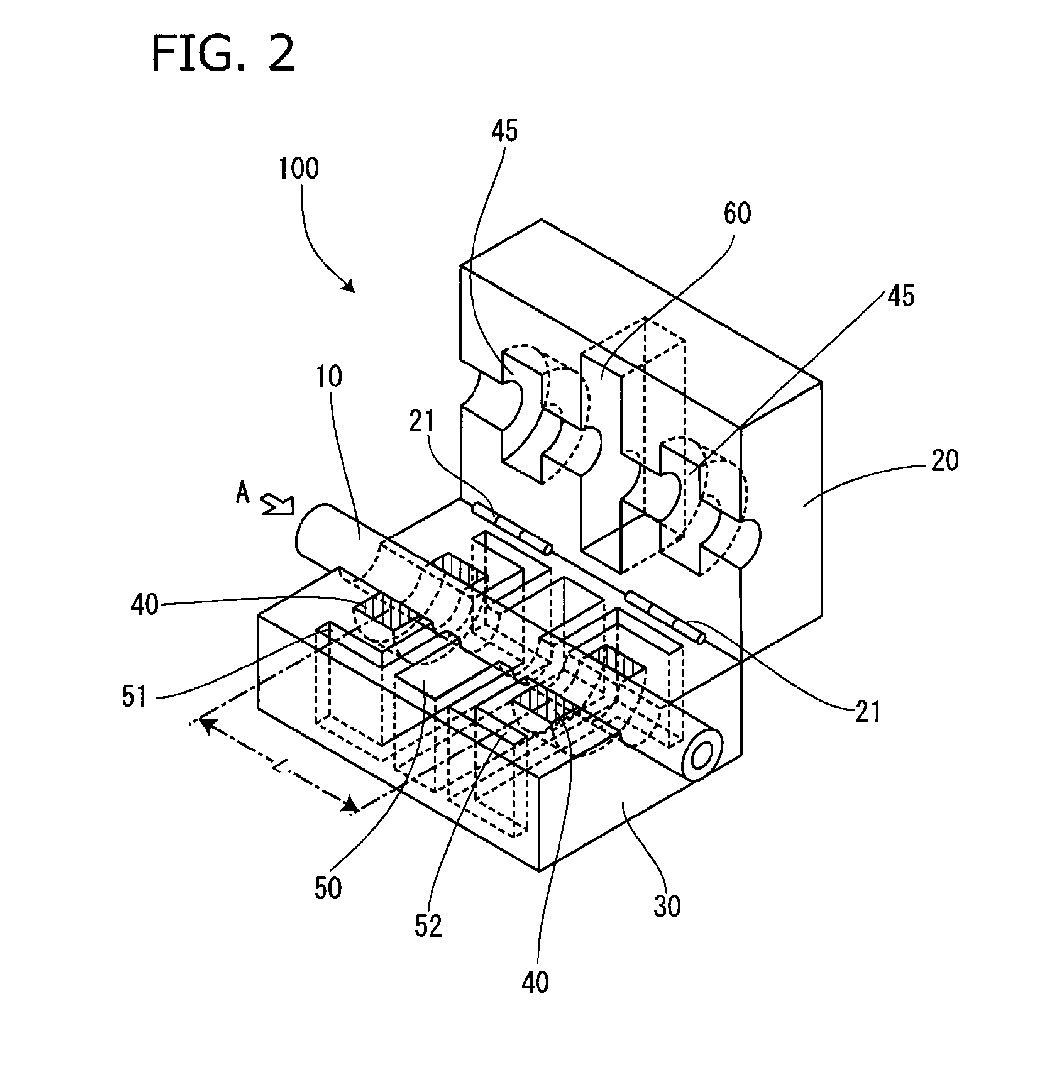
[0077]Subsequently, Embodiment 2 of the present invention will be explained with reference to FIG. 2 and FIG. 3B. Explanation will be given using the same reference numbers, to means and the like having similar function as in Embodiment 1. In Embodiment 2, similar to Embodiment 1, the lower sensor case 30 is equipped with the pair of the ultrasonic transmitting-receiving means 40, and a first ultrasonic attenuating means 50 is equipped at an intermediate portion between the pair, and the upper sensor case 20 is provided with a pair of the annular void portions 45 at the position corresponding to the pair of the ultrasonic transmitting-receiving means 40. The first ultrasonic wave attenuating means 50 is, similarly to Embodiment 1, specifically configured from the attenuating groove 50 formed at the lower sensor case 30. The attenuating groove 50 is formed from the groove-like spatial portion 50 by removing the material of the sensor case. Embodiment 2 of the present invention is cha...
embodiment 3
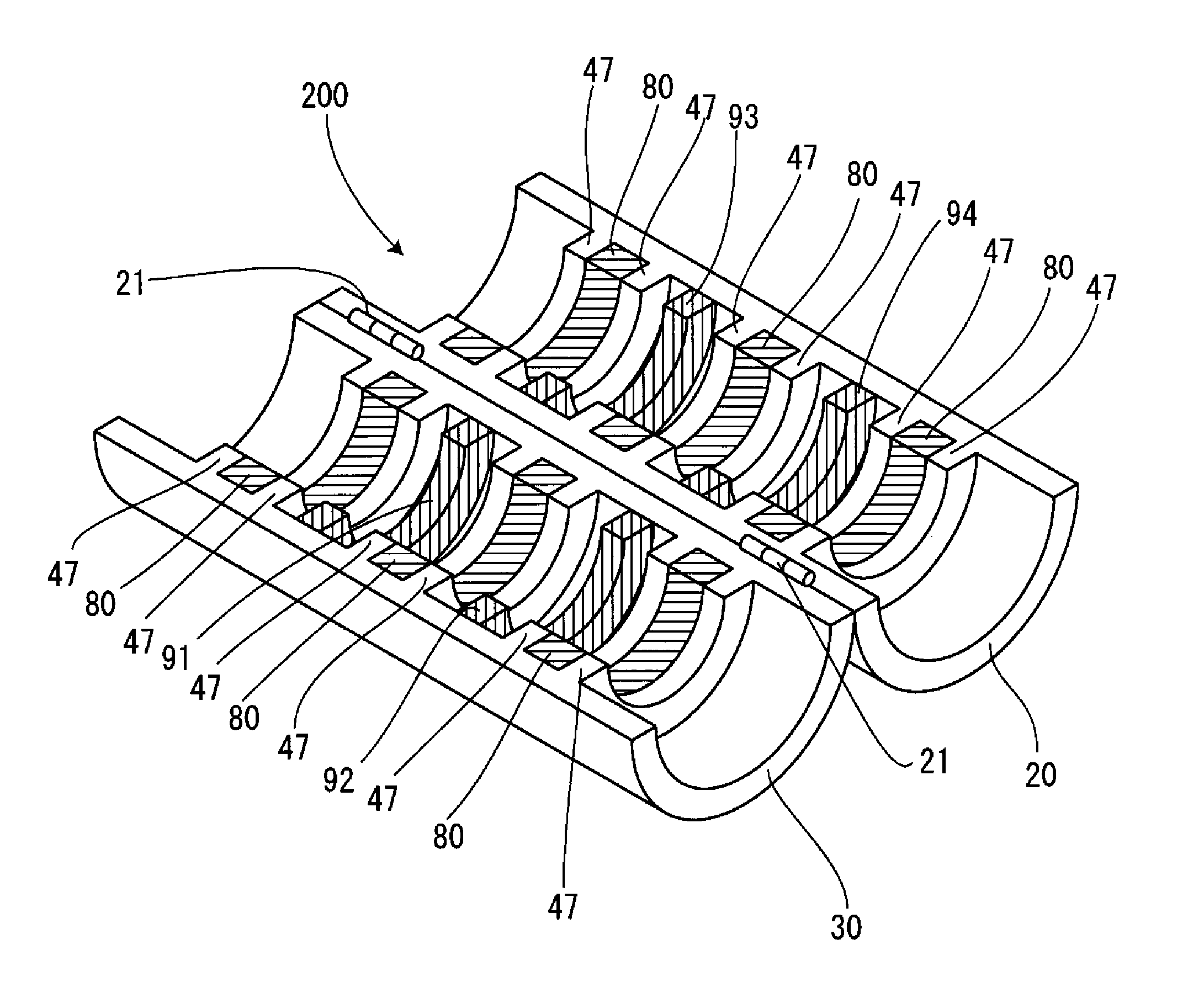
[0084]Subsequently, as Embodiment 3 of the present invention, a three-element type ultrasonic flow rate measuring device and ultrasonic flow rate measuring method will be explained. The one shown in Patent Document 1 proposes a two-element type, similarly to Embodiment 1 or Embodiment 2. The three-element type ultrasonic flow rate measuring device is shown in FIG. 6 through FIG. 8.
[0085]First, explanation will be given on the operating principle of the three-element type. The operating principle of the two-element type is as follows: the pair of the ultrasonic transmitting-receiving means 40 is arranged on the axis of the tube 10 in which the medium flows with a predetermined interval L therebetween; the other one of the element receives the ultrasonic signal transmitted from the one element and propagated through the medium; the transmitting element and the receiving element are switched to respectively detect the signal propagating through the flowing direction A of a fluid medium...
PUM
 Abstract
Description
Claims
Application Information
 - R&D
- Intellectual Property
- Life Sciences
- Materials
- Tech Scout
- Unparalleled Data Quality
- Higher Quality Content
- 60% Fewer Hallucinations
Browse by: Latest US Patents, China's latest patents, Technical Efficacy Thesaurus, Application Domain, Technology Topic, Popular Technical Reports.
© 2025 PatSnap. All rights reserved.Legal|Privacy policy|Modern Slavery Act Transparency Statement|Sitemap|About US| Contact US: help@patsnap.com