Particle Measurement Process and Apparatus

a particle measurement and process technology, applied in the direction of instruments, material analysis, electrostatic separation, etc., can solve the problems of shortening the lifetime and reliability of the charger, affecting the efficiency of the measurement process, and affecting the accuracy of the measurement results, so as to reduce the loss of ion, and increase the ion production

Active Publication Date: 2011-03-03
PEGASOR OY
View PDF6 Cites 36 Cited by
  • Summary
  • Abstract
  • Description
  • Claims
  • Application Information

AI Technical Summary

Benefits of technology

[0025]A preferred embodiment for ionizing the clean gas is to use corona discharger. The clean gas is advantageously fed with high speed from the close vicinity of the corona discharger so that the corona needle or equivalent is protected by the clean gas flow. The high-speed gas flow also increases ion production compared to a free-space corona discharging and decreases ion losses to the apparatus walls etc.
[0026]The electrical corona discharge may produce particles which disturb the measurement when the particle concentration in the measured gas is low. This may be the case e.g. when the process is used to monitor particle concentrations before and after a particle trap typically present in the diesel combustion engine exhaust duct. Such a measurement can provide an indication on the filtering capacity or maintenance need of the particle trap. In order to minimize the particle production by the corona discharge, it is advantageous to manufacture the corona needle and the nozzle surrounding the corona needle from a refractory metal or metal alloy, such as tungsten, rhenium, tantalum, molybdenum, iridium, niobium, ruthenium, hafnium, zirconium, vanadium, chrome, alloy C-103, alloy KBI-3, nickel-chrome alloys, tungsten carbide or similar. It is also advantageous to use dry clean gas flow to minimize particle production in the corona discharge.

Problems solved by technology

The problem of the described method is that the particles are charged by a charger placed inside the exhaust gas duct, where the charged easily gets soiled which soiling shortens the lifetime and reliability of the charger.
Varying particle concentration and constant ion generation cause problems in e.g. maintaining constant particle charging.
The formation of fine particles in the exhaust duct is a complicated process and making measurement in an environment with a greatly varying mass flow is very difficult.
The use of silicon electrodes in the sonic jet ionizer resulted in unacceptable levels of particle formation.
The problem with system is that the flow ratio of the aerosol and the clean air may change during the measurement e.g. due to the contamination of the filter.
The confront mixing of the ionized air and the aerosol by contrary jets is difficult, because the set-up is very sensitive to jet properties, like jet direction and jet velocity and thus the jets tend to be unstable.
Ion losses is such set-up are very high, typically more than 99% and even higher than 99.9%
The mixing in the system is inefficient and thus the ion losses are probably very high, typically more than 99.9%.
The problems with the prior art systems are: charger soiling, poor mixing of ionized air and aerosol, varying sample flow and high ion losses.
All these problems make the prior-art systems unstable especially for the on-line measurement of combustion engine exhaust gas particles.
The current systems are also large and cannot be used in e.g. monitoring the particle emissions from diesel vehicles.
The large mixing chamber in some prior-art systems also slows down the time response of the measurement result.

Method used


Image

  • Particle Measurement Process and Apparatus
  • Particle Measurement Process and Apparatus
  • Particle Measurement Process and Apparatus

Examples


Embodiment Construction

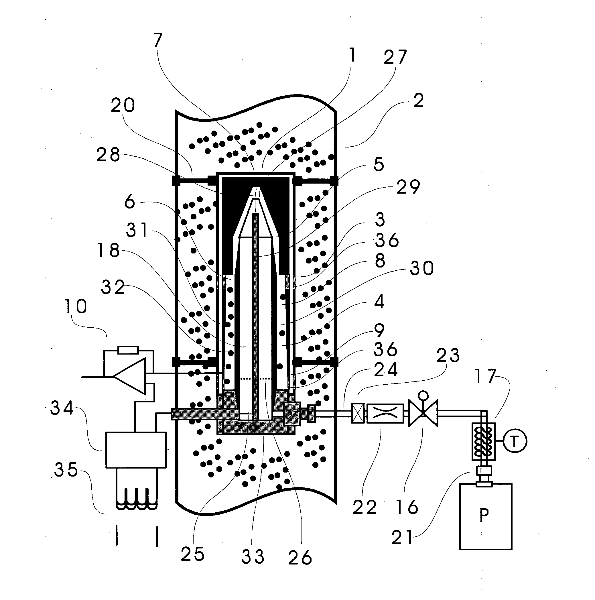
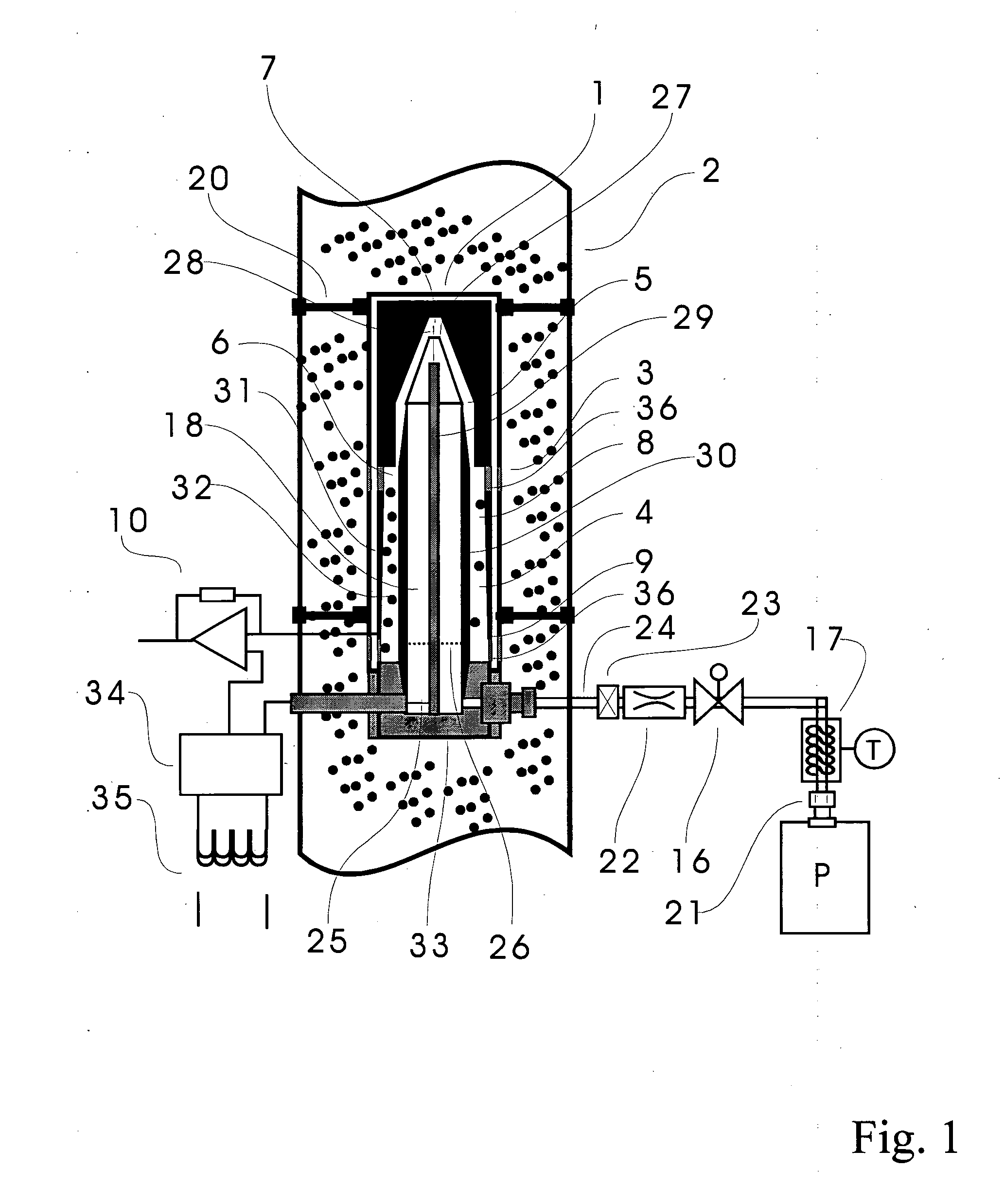
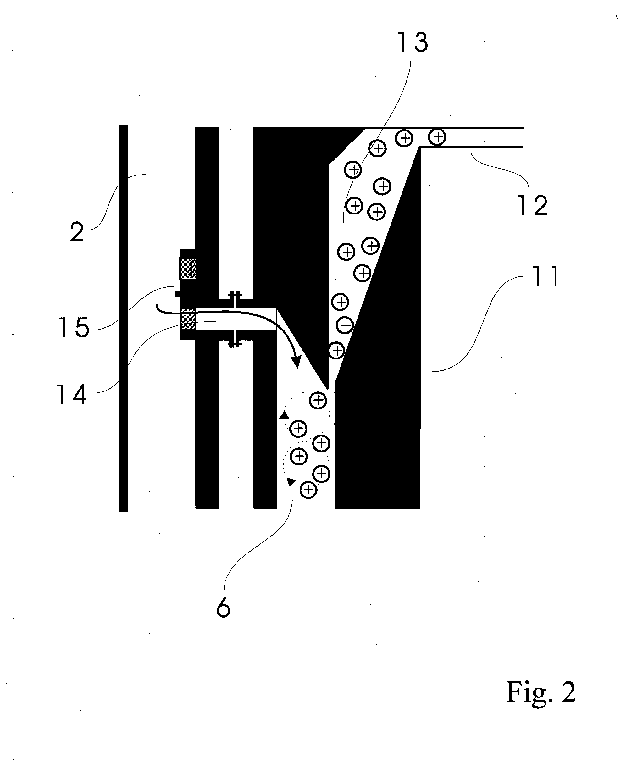
[0038]FIG. 5 shows the invented process as separated to different functional blocks. The sample flow NV is sucked from the duct or channel where the particle-containing gas flows via an ejector E. Pressurized air flow PI forms the main flow and an ionizer IG is used to ionize the pressurized air flow. The ionizer IG is preferably based on corona discharging, and the necessary high voltage for the corona discharge is generated with the high voltage source HV electrically isolated with the transformer M. The ionized air flow is mixed with the sample flow and the particles of the sample flow are charged in the charging chamber VK. It is to be understood that the charging chamber is really a functional block and the charging preferably takes place in the ejector essentially at the point where the main flow and the side flow meet each other. The ions not attached to the particles are removed by the ion trap IL before the flow PV escapes from the measurement apparatus. The current escapin...


PUM

PropertyMeasurementUnit
diameteraaaaaaaaaa
particle diameteraaaaaaaaaa
diametersaaaaaaaaaa

Abstract

A process for measuring particle concentrations in a gas using an ejector for producing an essentially constant sample flow and for efficient mixing of the particle-containing sample and and essentially clean, ionized gas. The invention also relates to an apparatus implementing such process. The process and the apparatus can be utilized for example in measuring particle concentrations in an exhaust system of a combustion engine.

Description

BACKGROUND OF THE INVENTION[0001]1. Field of Invention[0002]The invention relates to a process for measuring particle concentrations in an aerosol. The invention also relates to an apparatus implementing such process. The process and the apparatus can be utilized for example in measuring particle concentrations in an exhaust system of a combustion engine.[0003]2. Description of the State of the Art[0004]For various reasons, it is important to be able to measure fine particles, especially the ones born in combustion engines. The measurement activities are driven by the increasing concern of the potential health effects of fine particles and the health concerns have lead to fine particle emission limits. In the future the particle exhaust limits will continuously become tighter. Another need for fine particle measurements arises from the development of combustion engines and from real-time monitoring of combustion engines, especially diesel engines. Still another need for fine particl...

Claims


Application Information

Patent Timeline
Patent Type & Authority Applications(United States)
IPC IPC(8): G01N27/62
CPCG01N1/2252G01N2001/2264G01N15/0656B03C3/12B03C3/38B03C3/41B03C3/47B03C2201/06G01N15/1031G01N27/70
Inventor TIKKANEN, JUHA
Owner PEGASOR OY
Why Eureka
Try Eureka