Method for manufacturing a magnet-conductive device and apparatus thereof

a technology of magnet-conductive devices and manufacturing methods, which is applied in the manufacture of magnetic cores, auxiliary welding devices, paper/cardboard containers, etc., can solve the problems of large gap formed between adjacent silicon steel sheets, the eddy current loss and short issues of the riveting process, so as to prevent vibration and sound of wind shear, prevent iron loss, and avoid wind shear phenomenon

Inactive Publication Date: 2014-05-29
METAL INDS RES & DEV CENT
View PDF1 Cites 3 Cited by
  • Summary
  • Abstract
  • Description
  • Claims
  • Application Information

AI Technical Summary

Benefits of technology

[0003]The primary object of the present invention is to provide a method for manufacturing a magnet-conductive device and an apparatus thereof. By utilizing a glue dispenser and a stamping unit of the apparatus for manufacturing the magnet-conductive device, adjacent magnet-conductive plates enable to be mutually adhered and stackable to form the magnet-conductive device for prevention of iron loss, burr eddy-current loss and short phenomenon. Besides, when the present invention is applicable to a motor, wind shear phenomenon is avoidable so as to prevent vibrations and sounds of wind shear.
[0005]In this invention, the filling step is to provide the glue by the glue dispenser and make the glue adhered to the first magnet-conductive plate, and the adhering step is to make the glue adhered to the first magnet-conductive plate and the second magnet-conductive plate so that the gap between the first magnet-conductive plate and the second magnet-conductive plate is filled with the glue. By repeatedly performing the filling step and the adhering step, the desired stacking quantity is achieved to form the magnet-conductive device. In this invention, the first magnet-conductive plate and the second magnet-conductive plate are mutually coupled by means of pressure from the stamping unit and adherence of the glue. Therefore, the gap between the first magnet-conductive plate and the second magnet-conductive plate in the present invention is relatively smaller than that by using riveting process. The present invention enables to shorten current path, decrease ion loss and increase flux density. Additionally, the first magnet-conductive plate and the second magnet-conductive plate are spaced apart by the glue so that short issue is prevented and burr eddy-current loss is decreased. Furthermore, when the magnet-conductive device is applicable to a motor and the motor is in operation, owing to the reason that the gap between the first magnet-conductive plate and the second magnet-conductive plate is filled with the glue, the wind shear phenomenon is eliminated to prevent vibrations and sounds of wind shear.

Problems solved by technology

However, the magnet-conductive device manufactured by mentioned riveting process generates iron loss, burr eddy-current loss and short issues.
Additionally, a large gap is formed between adjacent silicon steel sheets.
When the magnet-conductive device is applicable to a motor and the motor is in operation, the gap between adjacent silicon steel sheets results in vibrations and sounds of wind shear.

Method used


Image

  • Method for manufacturing a magnet-conductive device and apparatus thereof
  • Method for manufacturing a magnet-conductive device and apparatus thereof
  • Method for manufacturing a magnet-conductive device and apparatus thereof

Examples


Embodiment Construction

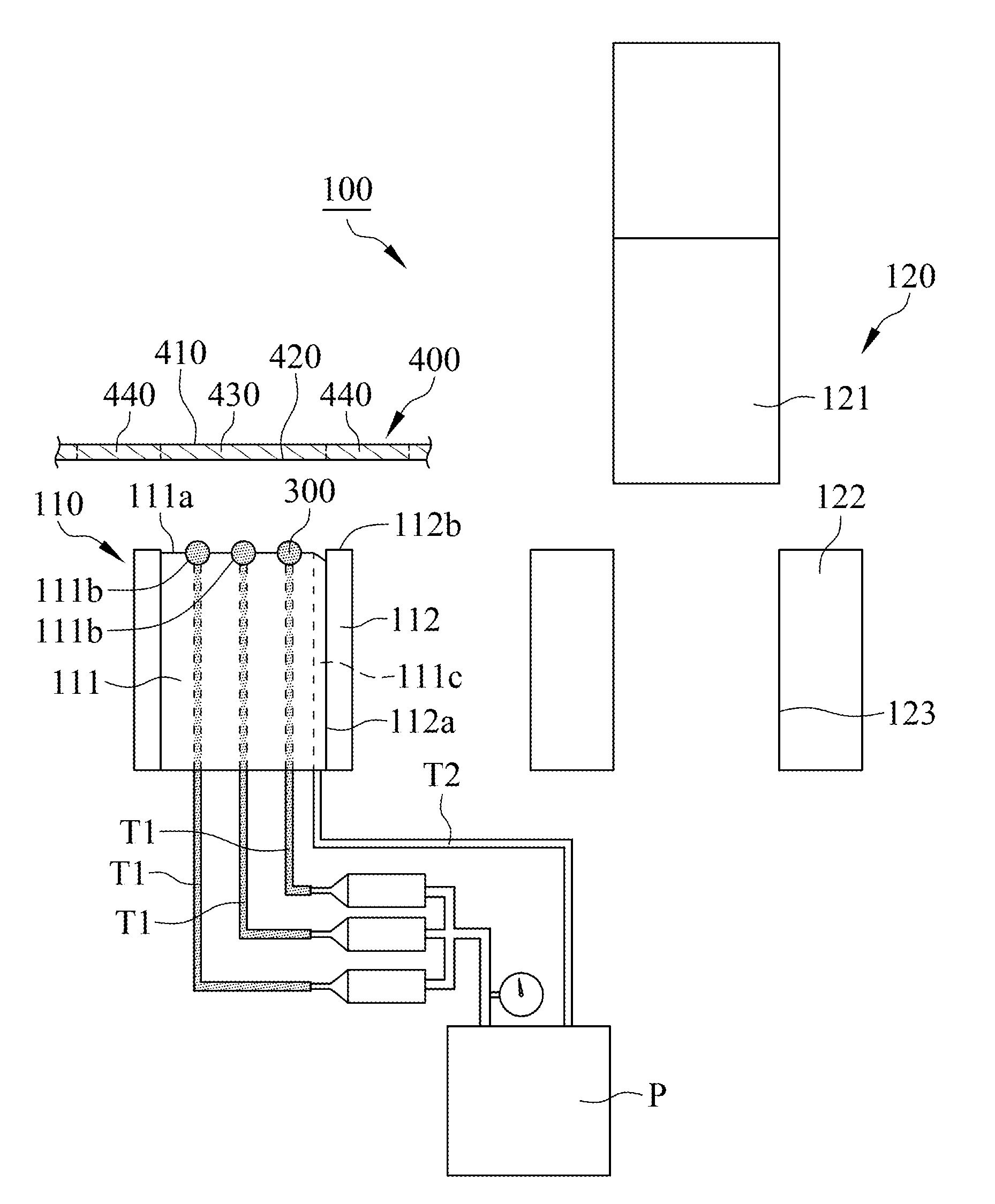
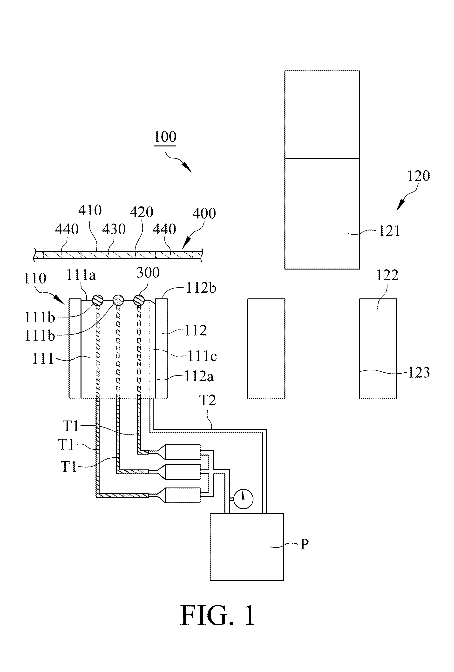
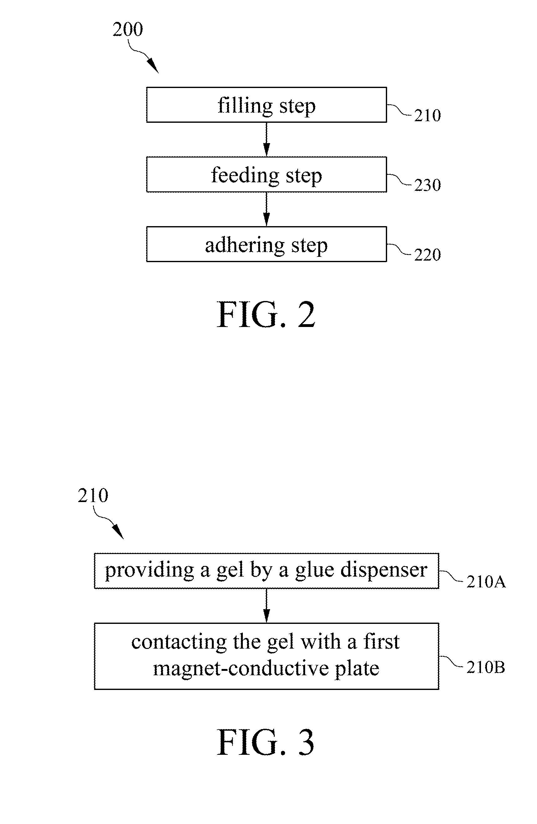
[0011]With reference to FIG. 1, an apparatus 100 for manufacturing a magnet-conductive device in accordance with a preferred embodiment of the present invention includes a glue dispenser 110 and a stamping unit 120. Please refer to FIG. 2, a method 200 for manufacturing the magnet-conductive device includes a filling step 210 and an adhering step 220.

[0012]Please refer to FIGS. 2 and 3, wherein the filling step 210 includes a first sub-step 210A of providing a glue by a glue dispenser and a second sub-step 210B of contacting the glue with a first magnet-conductive plate.

[0013]Please refer to FIGS. 1, 2, 3 and 4A, wherein in the first sub-step 210A of providing the glue by the glue dispenser, the glue dispenser 110 includes a base 111 and a substrate 112. Or, in another embodiment, the glue dispenser 110 merely possesses the base 111. In this embodiment, the substrate 112 comprises an accommodating slot 112a and a bearing surface 112b, the accommodating slot 112a is recessed to the b...


PUM

PropertyMeasurementUnit
magnet-conductiveaaaaaaaaaa
magnet-conductive aaaaaaaaaa
conductiveaaaaaaaaaa

Abstract

A method for manufacturing magnet-conductive device includes a filling step and an adhering step. The filling step includes providing a glue by a glue dispenser and contacting the glue with a first magnet-conductive plate to make the glue adhered to a lower surface of the first magnet-conductive plate. The adhering step includes making the lower surface of the first magnet-conductive plate face toward a second magnet-conductive plate, making the first magnet-conductive plate and the second magnet-conductive plate stackable from each other and adhering the first magnet-conductive plate and the second magnet-conductive plate via the glue. Eventually, by repeatedly performing the filling step and the adhering step, the desirable stacking quantity is achieved to form a magnet-conductive device.

Description

FIELD OF THE INVENTION[0001]The present invention is generally related to a method for manufacturing a magnet-conductive device. Particularly, the manufacturing method enables plural magnet-conductive plates to be stacked and adhered from each other by means of a glue dispenser and a stamping unit therefore forming the magnet-conductive device.BACKGROUND OF THE INVENTION[0002]A conventional method for manufacturing a magnet-conductive device is to form plural protrusions or bumps on an upper surface of each of plural silicon steel sheets and to form plural slots at a lower surface of each of the silicon steel sheets by punching process. Eventually, to engage adjacent silicon steel sheets by riveting process therefore forming the magnet-conductive device. However, the magnet-conductive device manufactured by mentioned riveting process generates iron loss, burr eddy-current loss and short issues. Additionally, a large gap is formed between adjacent silicon steel sheets. When the magne...

Claims


Application Information

Patent Timeline
Patent Type & Authority Applications(United States)
IPC IPC(8): H01F41/00
CPCB21D28/00H01F41/0213B32B7/12B32B2307/208Y10T156/10
Inventor TU, KUO-YINTSAI, HSING-CHIHWANG, HSIN-TECHEN, PIN-JYUNLIN, CHIH-HAOHSU, PO-FUHSIEH, CHING-HUA
Owner METAL INDS RES & DEV CENT
Why Eureka
Try Eureka