Sheet-medium Conveying Device and Image Forming Apparatus

Active Publication Date: 2013-05-02
OKI ELECTRIC IND CO LTD
View PDF14 Cites 8 Cited by
  • Summary
  • Abstract
  • Description
  • Claims
  • Application Information

AI Technical Summary

Benefits of technology

[0009]An object of the present invention is to provide a sheet-medium conveying device which can be easily accommodated in a main body of an image forming apparatus

Problems solved by technology

However, when folding the auxiliary tray and closing the main tray, a user sometimes feels cumbersome.
However, there are problems that when a sheet medium is put on the sheet-medium stacker surface formed by a combination of the main tray and the auxiliary tray, a tip (i.e., a front end) of the sh

Method used


Image

  • Sheet-medium Conveying Device and Image Forming Apparatus
  • Sheet-medium Conveying Device and Image Forming Apparatus
  • Sheet-medium Conveying Device and Image Forming Apparatus

Examples


first embodiment

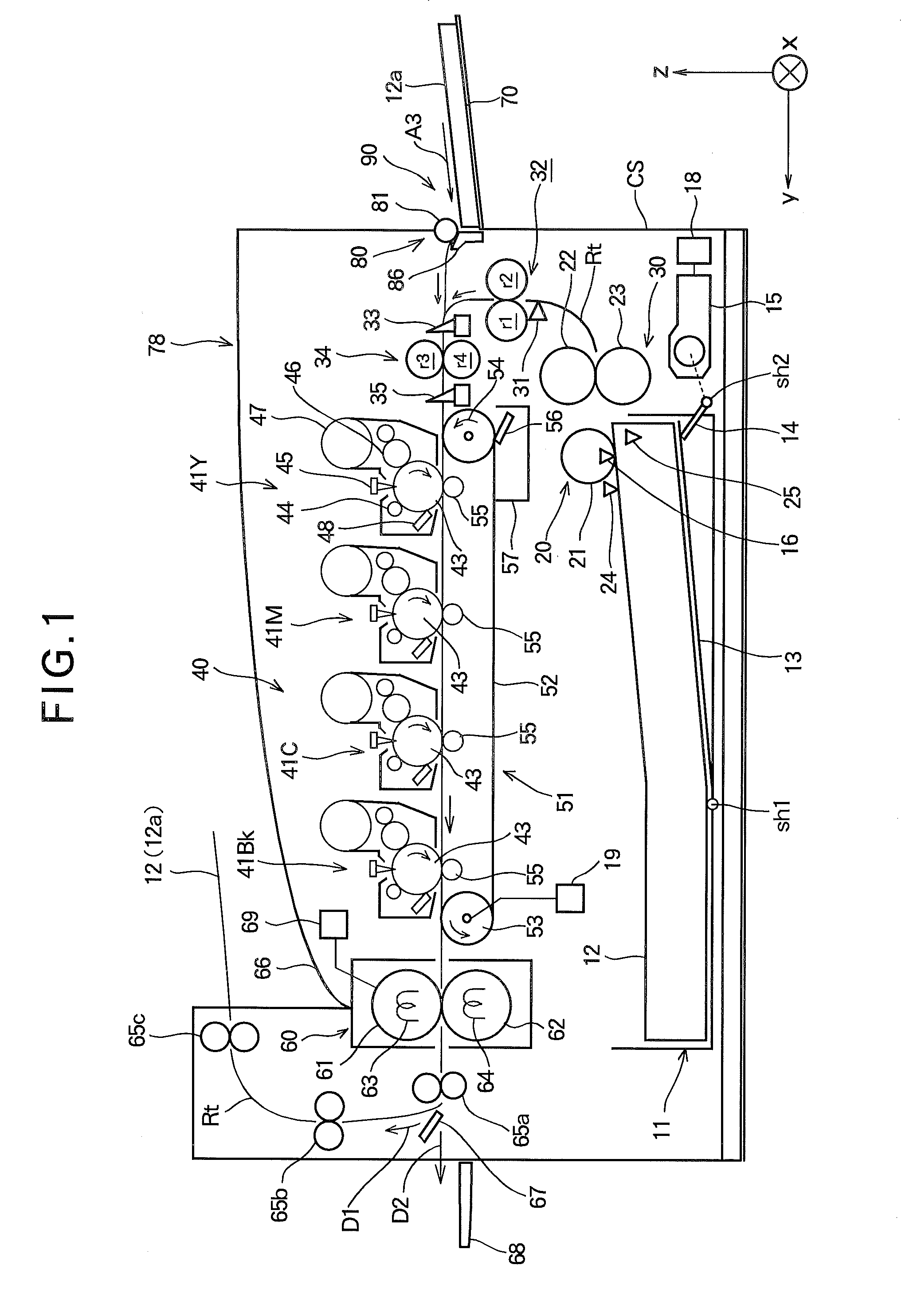
[0045]FIG. 1 is a diagram schematically showing internal structure of a color printer as an image forming apparatus according to a first embodiment.

[0046]As shown in FIG. 1, a sheet-medium cassette 11 forming a part of a first sheet-medium conveying device is provided at a lower part inside a main body (apparatus main body) 78 of the color printer so that the sheet-medium cassette 11 can be attached to and detached from the apparatus main body 78. The first sheet-medium conveying device has a function of a first sheet-medium feed unit. Sheet media 12 such as sheet papers are accommodated in the sheet-medium cassette 11. A sheet-medium stacker plate 13 is provided in the sheet-medium cassette 11 so as to be capable of being swung or rotated about a rotation shaft sh1 as a rotation center axis. The sheet media 12 are stacked on the sheet-medium stacker plate 13 in the sheet-medium cassette 11.

[0047]Guide members for regulating a position of the stacked sheet media 12 are provided in t...

second embodiment

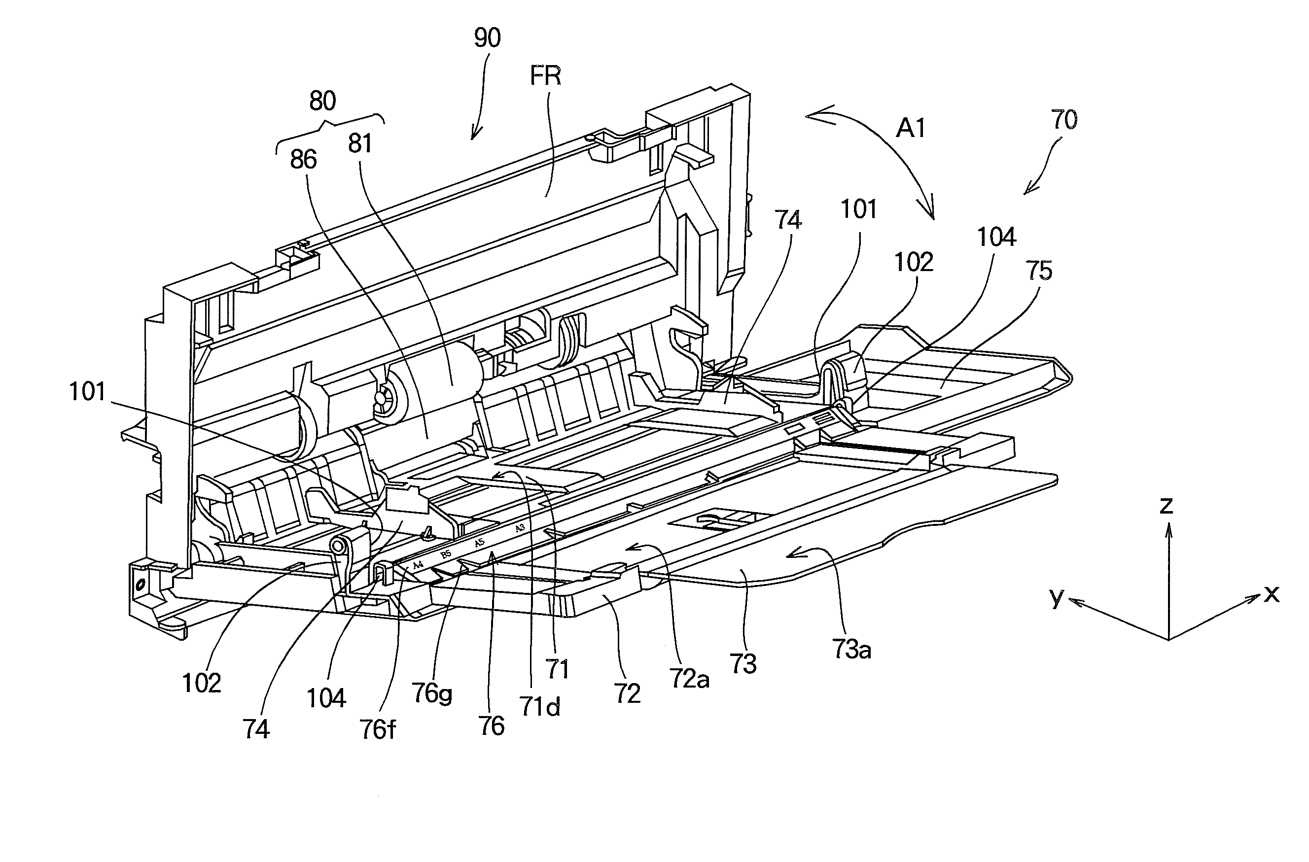
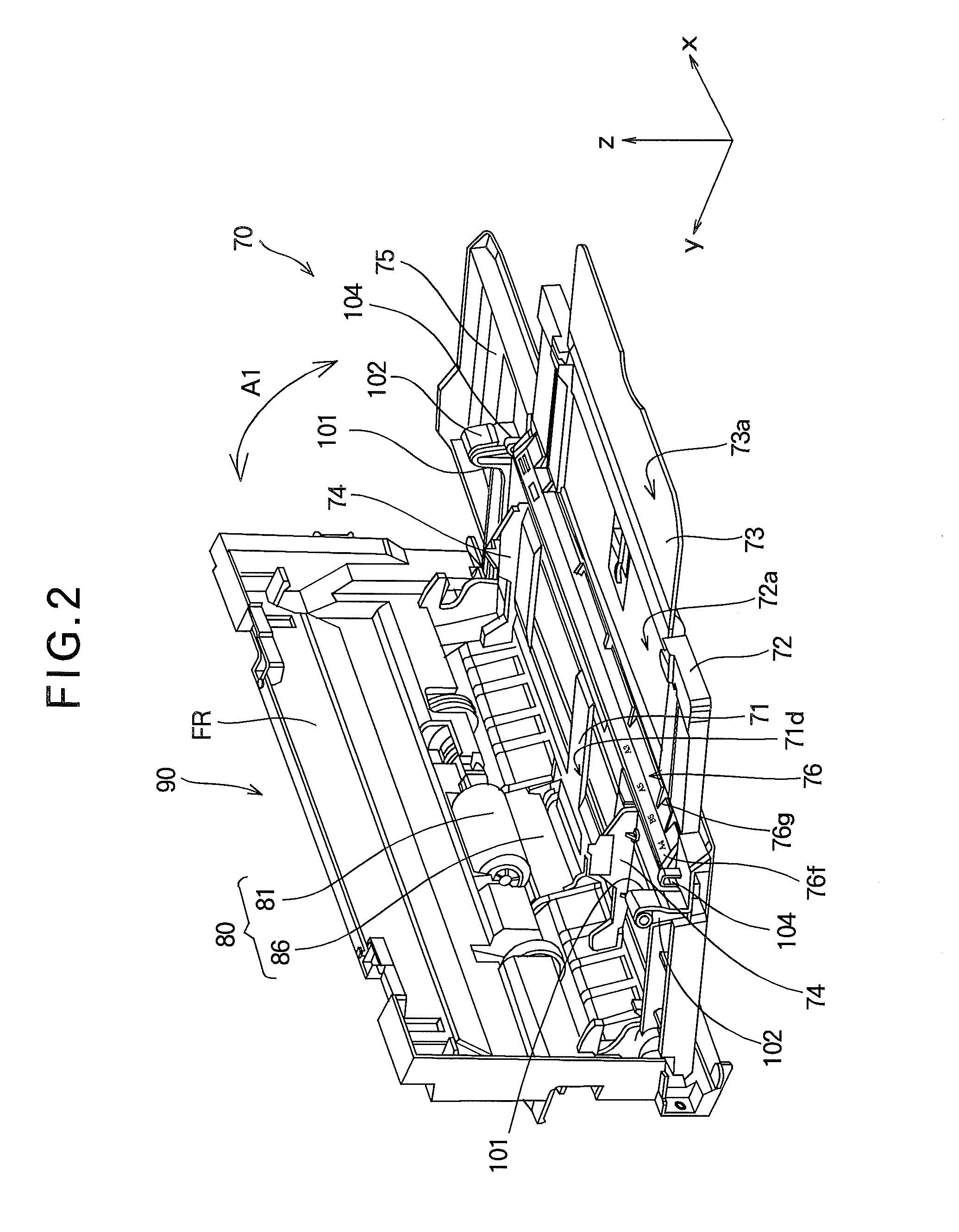
[0125]In the first embodiment, the main tray 71 is mounted to be rotatable to the exterior cover 75 and to be selectively located either at the depression position or at the sheet-medium feed position. The height of the shaft receiving parts 104 is set so that, when the main tray 71 is located at the depression position, the rear end part of the upper surface of the main tray 71 becomes the same as the front end part of the upper surface of the auxiliary stacker plate 76 or the rear end part of the upper surface of the main tray 71 becomes slightly lower than the front end part of the upper surface of the auxiliary stacker plate 76.

[0126]In the first embodiment, however, the main tray 71 and the auxiliary stacker plate 76 are both mounted to be rotatable to the exterior cover 75. Thus, when the main tray 71 is located at the depression position, a gap portion between the rear end part of the upper surface of the main tray 71 and the front end part of the upper surface of the auxilia...

modified examples

[0135]In the first and second embodiments, the cases where the sheet-medium conveying device is the sheet-medium feed tray 70 have been described. However, the present invention may be applied to another case where the sheet-medium conveying device is a sheet-medium output tray as a sheet-medium ejection mechanism.

[0136]Furthermore, in the first and second embodiments, the cases where the image forming apparatus is a color printer have been described. However, the present invention may be applied to other types of image forming apparatuses such as a photocopier, a facsimile and a Multifunction Peripheral (MFP).

[0137]The present invention is not limited to the aforementioned embodiments, but may be modified in various ways on the basis of the gist and spirit of the present invention.


PUM


Abstract

An image forming apparatus includes a sheet-medium conveying device, which has a first sheet-medium stacker part provided on a casing so as to be capable of being opened from and closed to the casing; a second sheet-medium stacker part provided on the first sheet-medium stacker part so as to be capable of being drawn from and inserted into the first sheet-medium stacker part; and an auxiliary member provided on the first sheet-medium stacker part so as to be capable of being moved, the auxiliary member being engaged with the second sheet-medium stacker part so as to be moved together with the drawing of the second sheet-medium stacker part so that the auxiliary member covers a gap portion between the main sheet-medium stacker surface and the expanded sheet-medium stacker surface when the second sheet-medium stacker part is in a drawn state.

Description

BACKGROUND OF THE INVENTION[0001]1. Field of the Invention[0002]The present invention relates to a sheet-medium conveying device and an image forming apparatus.[0003]2. Description of the Related Art[0004]In a conventional art, a sheet-medium cassette is mounted at a lower part in a main body (also referred to as an “apparatus main body”) of an image forming apparatus such as a color printer, and a sheet medium such as a sheet paper fed from the sheet-medium cassette is conveyed through a conveyance route along a plurality of image forming units. Toner images of different colors are formed on photosensitive drums of the image forming units respectively, the toner images are transferred from the photosensitive drums to the sheet medium, and then the toner images are fixed on the sheet medium by a fixing unit. As a result, a color image is formed on the sheet medium. Thereafter, the sheet medium is conveyed and then ejected from the apparatus main body onto an output stacker.[0005]Fur...

Claims


Application Information

Patent Timeline
IPC IPC(8): B65H1/04B65H5/00
CPCB65H1/04B65H2405/11164B65H2405/324B65H2405/32B65H2405/11B65H2405/1111B65H2405/1122B65H2407/21
Inventor MURAKAMI, TATSUYA
Owner OKI ELECTRIC IND CO LTD
Why Eureka
Try Eureka