
Liquid ejecting device

Active Publication Date: 2013-05-02
BROTHER KOGYO KK
View PDF2 Cites 10 Cited by
  • Summary
  • Abstract
  • Description
  • Claims
  • Application Information

AI Technical Summary

Benefits of technology

[0009]An aspect of the present invention may be advantageous in that a liquid ejecting device, in which adhesive liquid may be removed f

Problems solved by technology

As a result, the liquid remaining in nozzles may be dehydrated.
However, in the wiper unit in the inkjet recording apparatus, a form of the ink receiver having a cap, which is to contact the ejecting surface, may be complicated, and removing the remaining ink to clean t

Method used


Image

  • Liquid ejecting device
  • Liquid ejecting device
  • Liquid ejecting device

Examples


Example

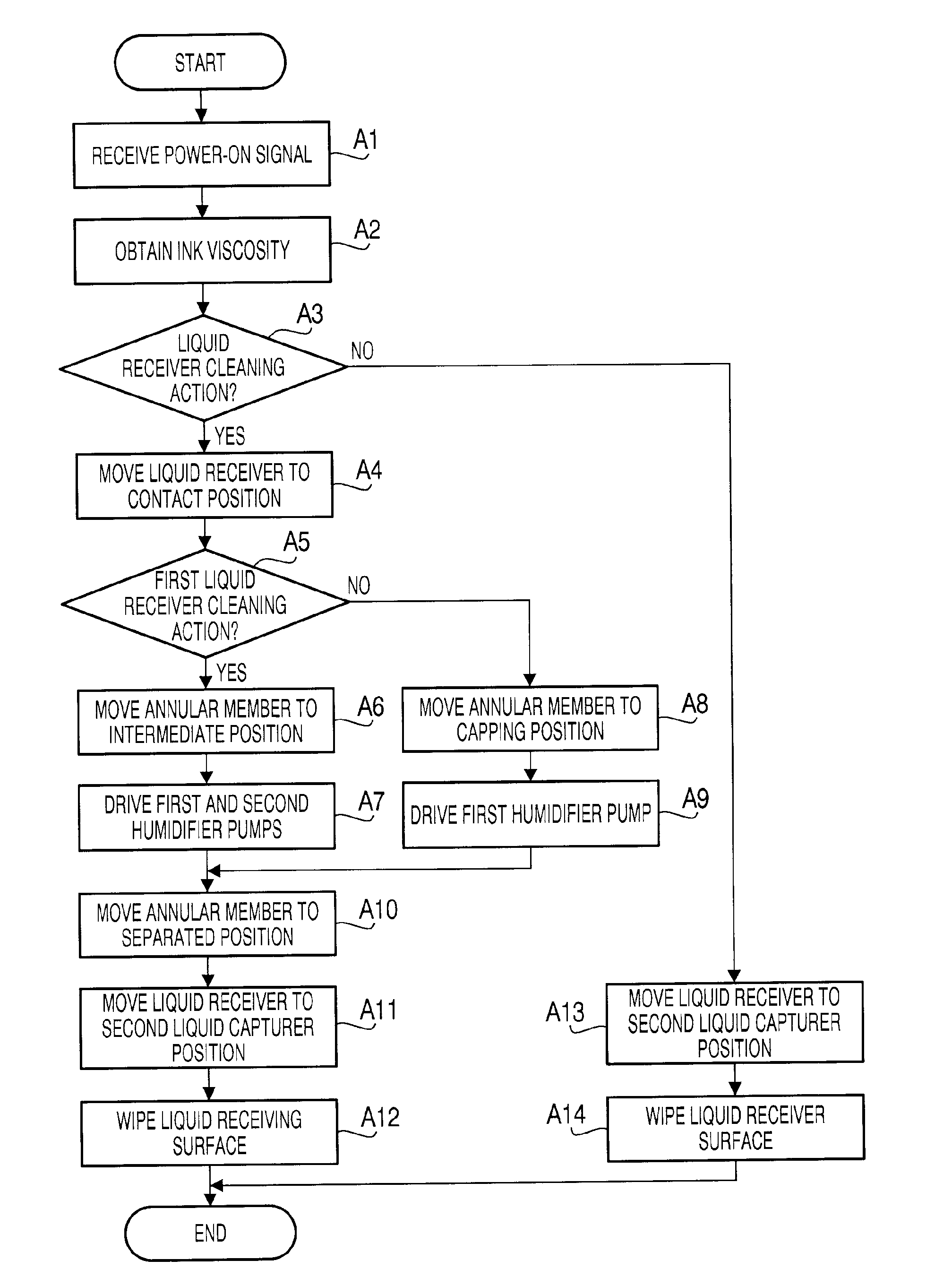
[0021]Hereinafter, an inkjet printer 1 as an embodiment of the liquid ejecting device according to the invention will be described with reference to the accompanying drawings.

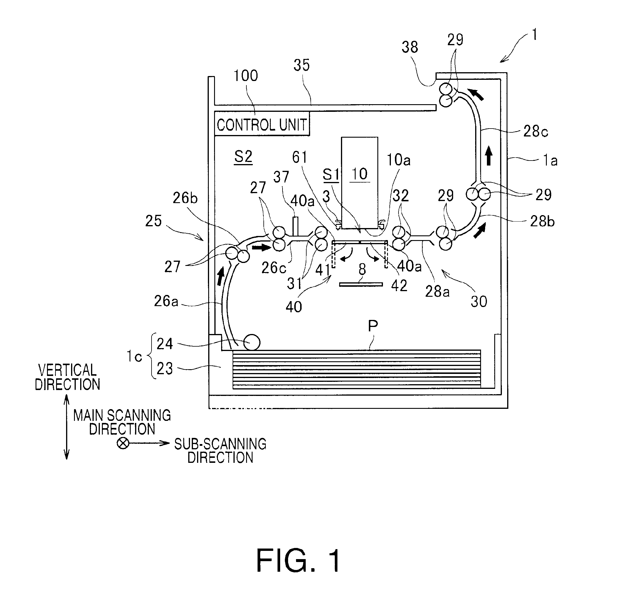
[0022]Firstly, an overall configuration of the inkjet printer 1 will be described with reference to FIG. 1. The inkjet printer 1 has a chassis 1a, which is formed in a shape of a rectangular box. On top of the chassis 1a, a discharge section 35 is provided, in a space enclosed by the chassis la, a sheet conveyer path is formed. In the sheet conveyer path, sheets P being recording media are conveyed from a feeder unit 1c to the discharge section 35. A flow of the sheet P being conveyed in the sheet conveyer path is indicated by thick arrows shown in FIG. 1,

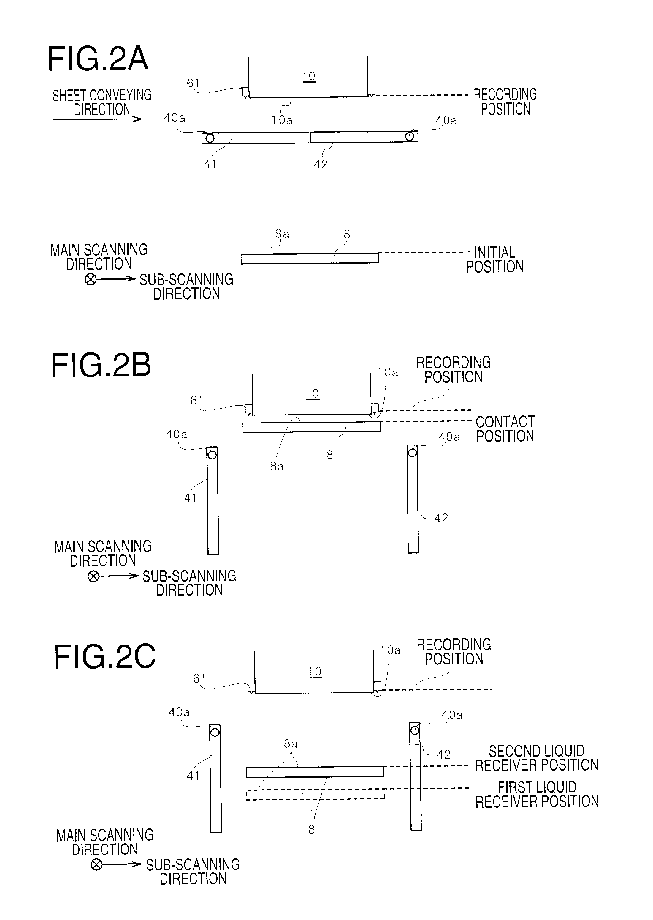
[0023]The chassis 1a accommodates an inkjet head 10, a conveyer unit 30, a platen 40, a guide unit 25, a cartridge (not shown), a head lifting unit 50 (see FIG. 8), a wiper unit 55 (see FIG. 3), a liquid, receiver 8, an annular member 61, a humidified air supp...


PUM


Abstract

A liquid ejecting device including a liquid ejecting head having an ejection surface, a liquid receiving member having a liquid receiving surface, an annular member for sealing an ejection surface, a positional relationship adjusting unit for adjusting a positional relationship between the ejection surface and the liquid receiving surface, an air inlet, a humidified air supplying unit, a cleaning unit, a viscosity information obtainment unit, and a control unit is provided. The control unit conducts a liquid receiving surface cleaning action including control of the positional relationship adjusting unit for adjusting the positional relationship between the ejection surface and the liquid receiving surface to form a first positional relationship, the humidified air supplying unit for supplying humidified air to the ejection space, and the cleaning unit for removing the liquid received on the liquid receiving surface.

Description

CROSS REFERENCE TO RELATED APPLICATION [0001]This application claims priority from Japanese Patent Application No. 2011-238628, filed on Oct. 31, 2011, the entire subject matter of which is incorporated herein by reference.BACKGROUND [0002]1. Technical Field[0003]An aspect of the present invention relates to a liquid ejecting device, which is capable of ejecting liquid..[0004]2. Related Art[0005]A liquid ejecting device to eject ink from ejecting openings (e.g., nozzles) formed on an ejecting surface of a liquid ejecting head is known. In order to avoid desiccation of the liquid remaining in the nozzles, a method to separate an ejection space, to which the ejecting surface is exposed, from an outer space, may be suggested. For example, the nozzle surface and the ejection space may be sealed from the outer space by a nozzle coven[0006]With the nozzle cover, the liquid ejected from the nozzles may be received on a liquid receiver (i.e., the nozzle cover). The liquid remaining on the l...

Claims


Application Information

Patent Timeline
IPC IPC(8): B41J29/38
CPCB41J2/175B41J2/18B41J2002/16555B41J2/16585B41J2/16552
Inventor KYOTANI, TADAO
Owner BROTHER KOGYO KK
Learn More