
Endovascular catheter and method of use

a technology of endovascular catheters and catheters, applied in the field of electrode-surgical working ends and catheters, can solve problems such as rapid heart ra

Inactive Publication Date: 2006-04-20
TRUCKAI CSABA +1
View PDF0 Cites 32 Cited by
  • Summary
  • Abstract
  • Description
  • Claims
  • Application Information

AI Technical Summary

Benefits of technology

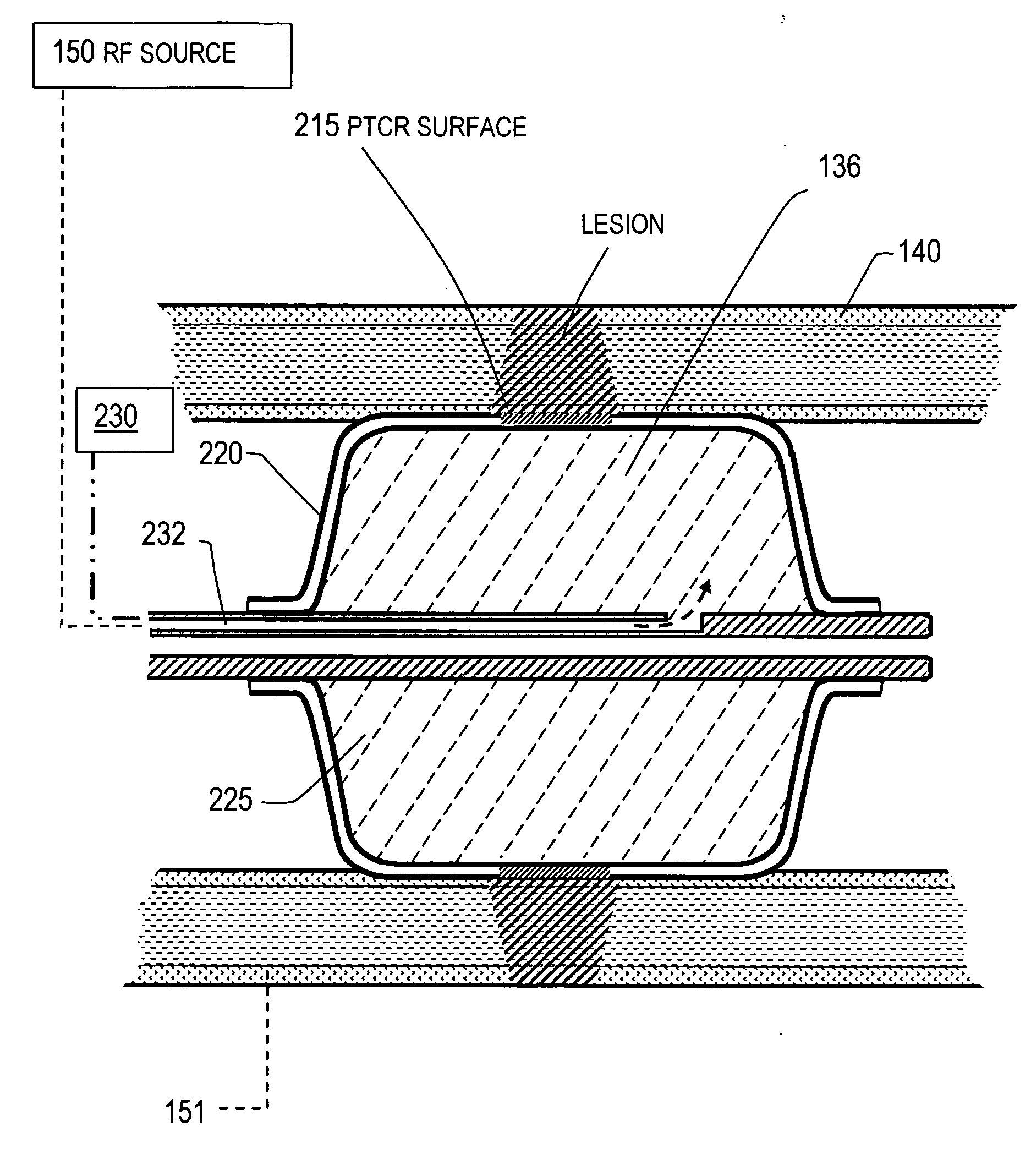
[0010] In operation, it can be understood that current flow through the PTCR surface will cause active Rf energy (ohmic heating) in the engaged tissue until the point in time that any portion of the matrix is heated to the predetermined range that substantially reduces the conductance of the PTCR material. This effect will occur across the surface of the PTCR material thus allowing each PTCR portion to deliver an independent level of power therethrough. This instant, localized reduction of Rf energy application can be relied on to prevent any dehydration and desiccation of tissue proximate to the electrosurgical surface. The system eliminates the possibility of tissue charring and the potential of emboli. In operation, the working end can modulate the application of Rf energy to the engaged tissue to create a lesion having a predetermined depth and shape.
[0012] In another embodiment, the catheter working end carries an electrosurgical surface comprising a pressure sensitive variably resistive material for controlling or limiting Rf current flows in tissue based on engagement pressure. Such a pressure sensitive material also can assist in preventing arcing and tissue desiccation.
[0015] The instrument and method of the invention can treat endocardial tissues without tissue charring, thus preventing any possibility that charred material will be migrate and cause the risks, such as in embolic stroke.
[0016] The instrument and method advantageously can create a lesion in endocardial tissues for blocking conduction pathways that is substantially narrow and substantially deep within cardiac tissue.

Problems solved by technology

When this happens, the impulse begins to travel abnormally in a rapid, circular manner, causing a rapid heart rate.

Method used


Image

  • Endovascular catheter and method of use
  • Endovascular catheter and method of use
  • Endovascular catheter and method of use

Examples


Embodiment Construction

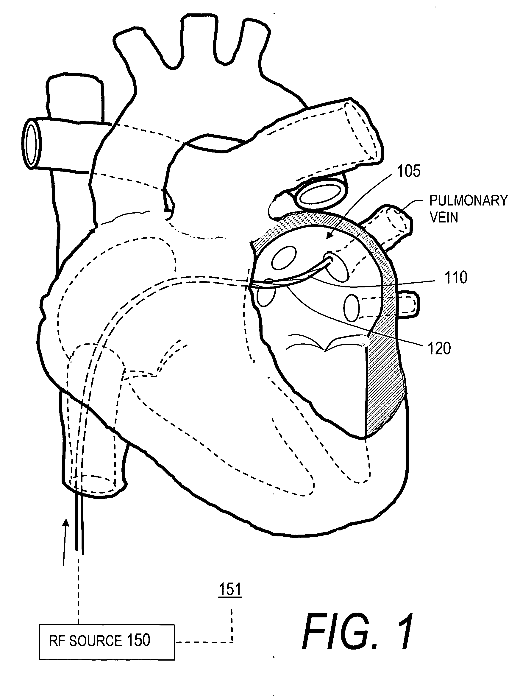
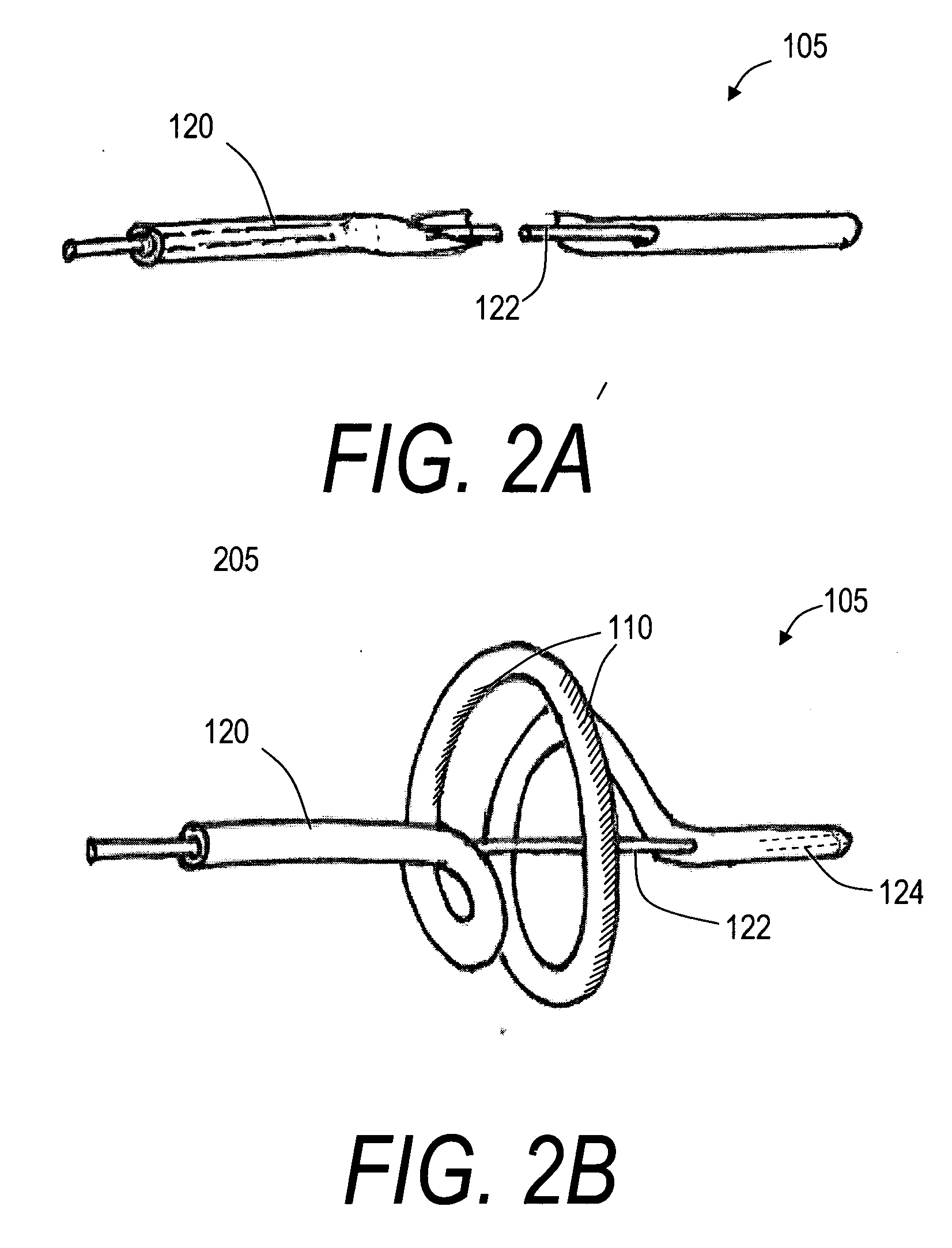
[0030] 1. Type “A” catheter with PTCR electrosurgical surface. FIG. 1 illustrates a Type “A” electrosurgical catheter 100 with a distal working end region 105 having a PTCR electrosurgical surface 110 corresponding to the invention after being guided over a guidewire to the left atrium 112. The scope of the invention extends to any endoluminal catheter that includes any electrical conductor coupled to a voltage source that has such a PTCR surface for controlling Rf current flow and the resultant ohmic heating of engaged tissue. The cross-section of the catheter sleeve 100 can be a suitable dimension, for example, from 2 to 10 French OD. The catheter can have a bore therein dimensioned to slide over a guidewire.

[0031] The PTCR electrosurgical surface 110 is a polymeric composition that is doped with conductive particles. The PTCR composition is described in more detail in the co-pending patents listed in the Section above titled CROSS-REFERENCE TO RELATED APPLICATIONS. In one embodi...


PUM


Abstract

An electrosurgical medical device and method for treating cardiac arrhythmias. In one embodiment, an elongate catheter has a distal shaft end or balloon that carries an electrosurgical energy delivery surface comprising at least one electrode with a positive temperature coefficient of resistance (PTCR) surface and / or an electrode with a pressure sensitive variable resistance to provide a smart surface for controlling Rf current flow at the interface of electrosurgical surface and the tissue. The electrosurgical surface then can limit or modulate Rf energy delivery through the surface in response to the temperature of the tissue or the engagement pressure of the surface against the engaged tissue. In operation, the smart electrosurgical surface can prevent arcing at the electrode-tissue interface, and thus control ohmic heating to prevent tissue desiccation, charring and emboli formation.

Description

CROSS-REFERENCE TO RELATED APPLICATIONS [0001] This application claims benefit the following Provisional U.S. patent applications: Ser. No. 60 / 601,497 filed Aug. 14, 2004 titled Endovascular Catheter and Method of Use and Ser. No. 60 / 602,500 filed Aug. 17, 2004 titled Endovascular Catheter and Method of Use. This application is a continuation-in-part of co-pending U.S. patent application Ser. No. 10 / 032,867 filed Oct. 22, 2001; and is a continuation-in-part of U.S. patent application Ser. No. 10 / 351,449 filed Jan. 22, 2003; and is a continuation-in-part of U.S. patent application Ser. No. 10 / 441,519 filed May 20, 2002; and is a continuation-in-part of U.S. patent application Ser. No. 10 / 781,925 filed Feb. 14, 2004. All of the above applications are incorporated herein by this reference and made a part of this specification.BACKGROUND OF THE INVENTION [0002] 1. Field of the Invention [0003] The present invention relates to electrosurgical working ends and catheters for treatment of c...

Claims


Application Information

Patent Timeline
IPC IPC(8): A61B18/14
CPCA61B18/1442A61B18/1482A61B18/1492A61B2018/00351A61B2019/464A61B2018/0022A61B2090/064
Inventor TRUCKAI, CSABASHADDUCK, JOHN H.
Owner TRUCKAI CSABA
Learn More