
System and method for gateway RF diversity using a configurable spot beam satellite

a satellite and spot beam technology, applied in the field of gateway rf diversity using a configurable spot beam satellite, can solve the problems of reducing the service availability of users, affecting the service quality of users,

Active Publication Date: 2013-05-02
HUGHES NETWORK SYST
View PDF2 Cites 49 Cited by
  • Summary
  • Abstract
  • Description
  • Claims
  • Application Information

AI Technical Summary

Benefits of technology

This patent describes a system and method for using a configurable spot beam satellite for gateway RF diversity. The system includes a satellite, two gateways, and a diversity control function. The first gateway connects to a first VSAT population through the satellite using a first gateway spot beam and a first user spot beam set. The diversity gateway is located outside of the first gateway spot beam for the first gateway. When the first gateway experiences service interruption, the diversity control function commands the satellite to connect the first user spot beam set for the first gateway to a diversity gateway spot beam to ensure continued service. The technical effect of this invention is to provide better reliability and coverage in areas where the first gateway may fail.

Problems solved by technology

Satellite communication systems may be susceptible to various types of service disruption, such as that caused by, for example, rain fade attenuation.
Rain fade at a satellite ground station, or gateway, may reduce service availability for users in user spot beam sets served by that gateway.
The provision of large antennas and amplifiers may be expensive, and even when coupled with ACM, may not provide the target service availability for sufficiently rainy gateway sites.
There may be limited infrastructure access that makes it difficult to find a cost-effective site for an RF diversity gateway within the gateway spot beam, due to lack of facilities, power, terrestrial communication access, staffing, security, and so on.
For high capacity satellite systems that employ many gateway spot beams, the use of RF diversity gateways may result in an RF diversity gateway being replicated in each gateway spot beam where necessary to achieve the targeted service availability, resulting in considerable capital and operating costs for RF diversity sites.

Method used


Image

  • System and method for gateway RF diversity using a configurable spot beam satellite
  • System and method for gateway RF diversity using a configurable spot beam satellite
  • System and method for gateway RF diversity using a configurable spot beam satellite

Examples


Embodiment Construction

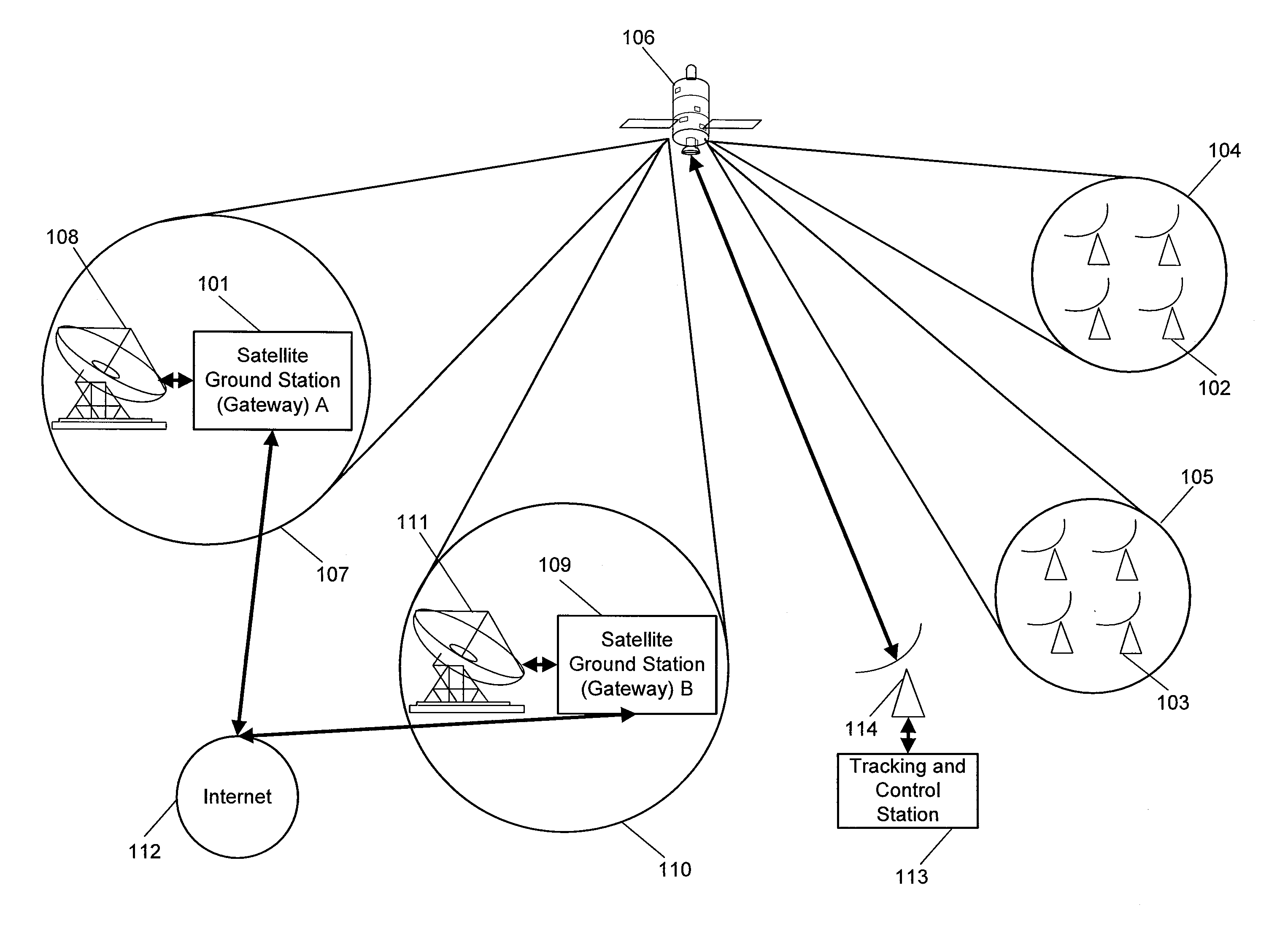
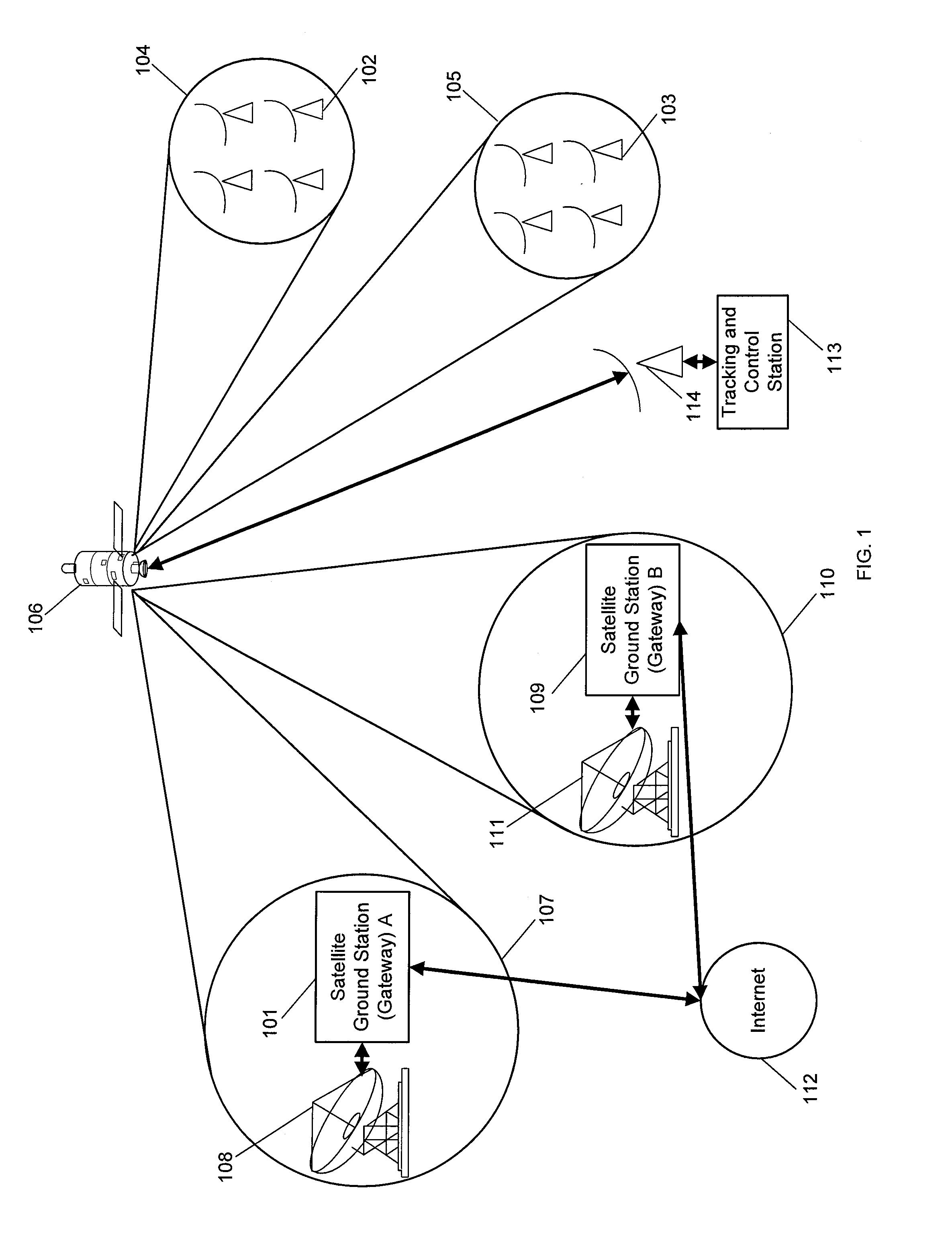
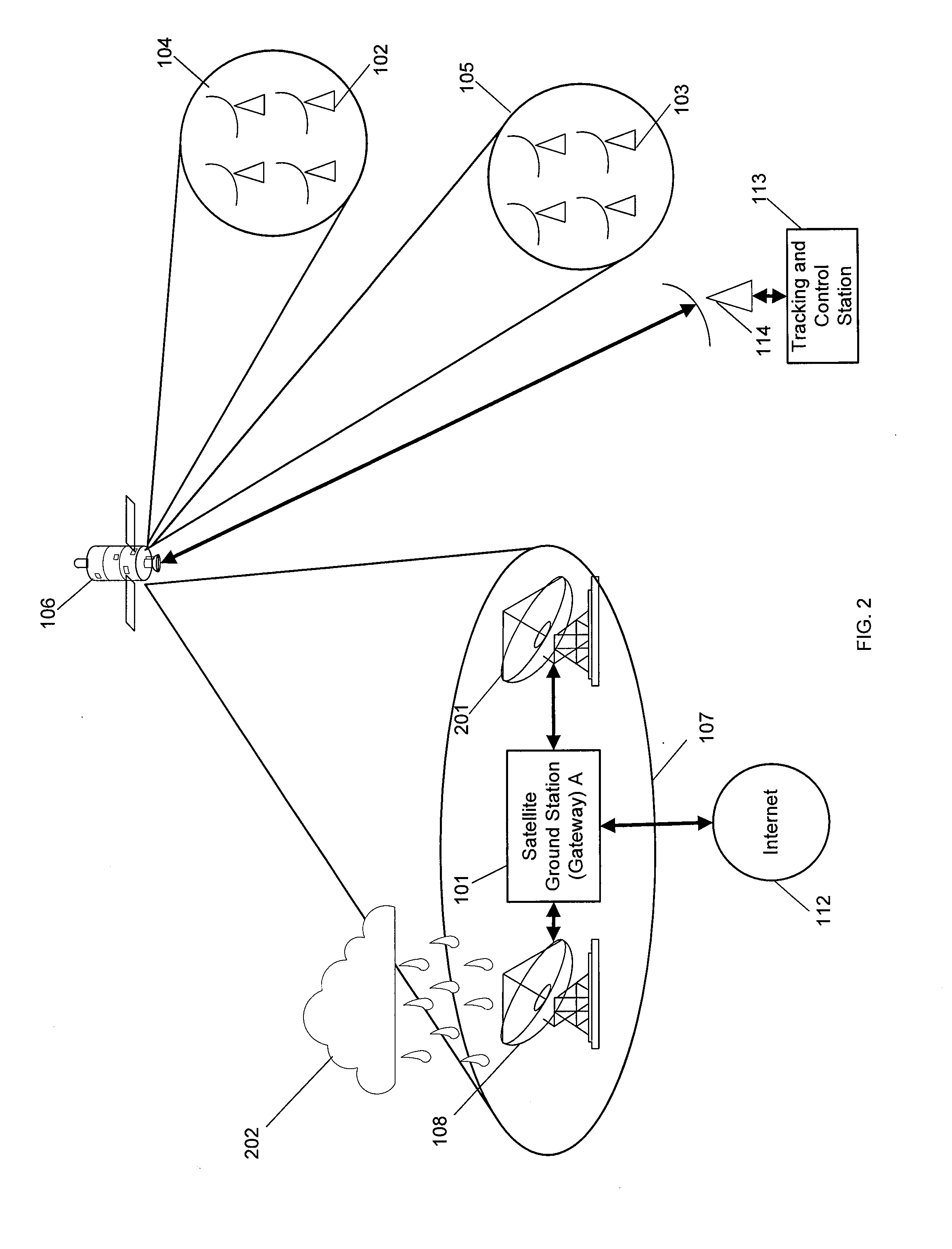
[0016]FIG. 1 depicts an exemplary satellite communications system. The satellite communications systems may include a satellite ground station, or gateway, A 101, a Very Small Aperture Terminal (VSAT) population A 102, VSAT population B 103, a user spot beam set A 104, a user spot beam set B 105, a satellite 106, a gateway spot beam A 107, an RFT A 108, a gateway B 109, a gateway spot beam B 110, an RFT B 111, the internet 112, a telemetry, tracking and control station 113, and tracking and control RFT 114.

[0017]The gateway A 101 may be a satellite ground station, hub or gateway for a satellite communications system, and may be connected to the VSATs in the VSAT population A 102 through the satellite 106. Feeder links through the gateway spot beam A 107 may carry data between the gateway A 101 and the satellite 106, and may include a forward uplink for transmitting data from a gateway A 101 to the satellite 106, and a return downlink for transmitting data from the satellite 106 to a...


PUM


Abstract

A system for gateway RF diversity using a configurable spot beam satellite including a satellite, a first gateway connected to a first VSAT population through the satellite by a first gateway spot beam and a first user spot beam set, a diversity gateway located outside of the first gateway spot beam for the first gateway, and a diversity control function to command the satellite to connect the first user spot beam set for the first gateway to a diversity gateway spot beam when the first gateway experiences service interruption.

Description

BACKGROUND[0001]Satellite communication systems may be susceptible to various types of service disruption, such as that caused by, for example, rain fade attenuation. The higher frequencies used in modern high throughput satellite systems may be more attenuated by rain than are lower frequencies used in other systems. For example, rain attenuation may be more severe at Ka-band or V-band than at L-band or C-band. Rain fade at a satellite ground station, or gateway, may reduce service availability for users in user spot beam sets served by that gateway. This may be partially mitigated, for example, through application of adaptive coding and modulation (ACM) techniques, which may apply robust modulation and / or coding when necessary to overcome atmospheric effects. This may provide improved link availability at the cost of reduced link capacity. Uplink power control (ULPC) systems may also be provided at a gateway's RF Terminal (RFT) to compensate for uplink attenuation by increasing up...

Claims


Application Information

Patent Timeline
IPC IPC(8): H04B7/185
CPCH04B7/18528H04B7/18513H04B7/18515
Inventor ROOS, DAVEMORRIS, ADRIANKAY, STANLEYCHOQUETTE, GEORGE
Owner HUGHES NETWORK SYST
Learn More