Fuel Injector With Needle Control System That Includes F, A, Z and E Orifices

a technology of fuel injectors and control systems, applied in fuel injection apparatus, charge feed systems, spraying apparatus, etc., can solve the problems of increased complexity and difficulty in manufacture, less than satisfactory performance relative to the counterpart three-way valve control strategy, and unacceptable performance variance of fuel injectors

Active Publication Date: 2013-05-09
CATERPILLAR INC
View PDF10 Cites 13 Cited by
  • Summary
  • Abstract
  • Description
  • Claims
  • Application Information

AI Technical Summary

Benefits of technology

[0006]In one aspect, a fuel injector includes an injector body that defines a fuel inlet, at least one nozzle outlet and a drain outlet, and has disposed therein a nozzle chamber, a needle control chamber, an intermediate chamber and a buffer chamber. The needle control chamber is fluidly connected to the fuel inlet by a first pathway that includes a Z orifice, and the needle control chamber is fluidly connected to the fuel inlet by a second pathway that includes an F orifice, the intermediate chamber and an A orifice. An electronically controlled valve is attached to the injector body and includes a control valve member movable between a first position in contact with a valve seat and a second position out of contact with the valve seat. The needle control chamber is fluidly connected to a drain outlet by a third pathway that includes the A orifice, the intermedia

Problems solved by technology

In general, a three way valve version can provide greater performance capabilities relative to a two way valve counterpart, but does so at the expense of increased complexity and difficultly to manufacture, especially mass producing fuel injectors with consistent performance behaviors.
This motivation quickly lead to a problem associated with a general desirability to end injection events abruptly, which is accomplished by quickly raising p

Method used


Image

  • Fuel Injector With Needle Control System That Includes F, A, Z and E Orifices
  • Fuel Injector With Needle Control System That Includes F, A, Z and E Orifices
  • Fuel Injector With Needle Control System That Includes F, A, Z and E Orifices

Examples


Embodiment Construction

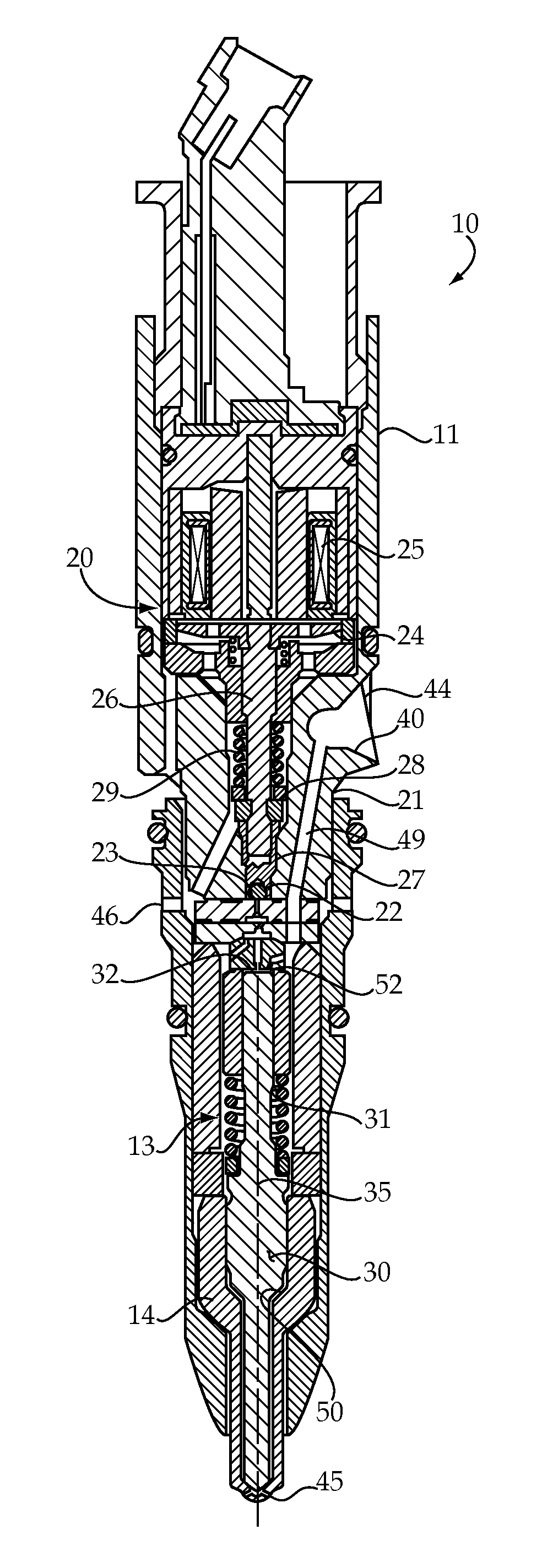
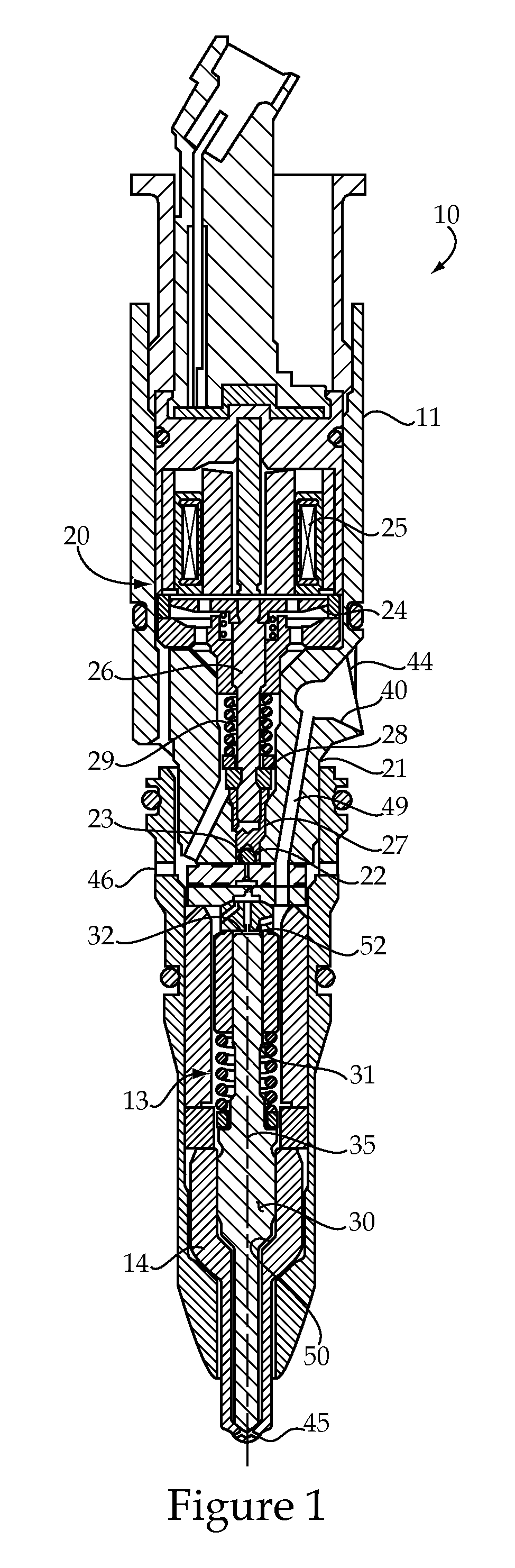
[0016]Referring to FIGS. 1 and 2, a fuel injector 10 includes an injector body that defines a fuel inlet 44, at least one nozzle outlet 45 and a low pressure drain outlet 46. Fuel inlet 44 includes a conical seat 40 to facilitate connection between fuel injector 10 and a common rail via a quill of a type well known in the art. Low pressure drain outlet 46 would be fluidly connected to tank to return for recirculation any fuel expended for the control function and / or from leakage. The nozzle outlets 45 would be positioned in the combustion space of a compression ignition engine to facilitate direct fuel injection into the engine cylinder. Fuel injector 10 includes a direct operated check 13 of a type briefly described in the background section. Disposed within injector body 11, which includes all hardware except electrical and moving components, are a number of fluid passageways and chambers. Among these are a nozzle chamber 50, a needle control chamber 52, an intermediate chamber 54...


PUM


Abstract

A common rail fuel injector includes a needle valve member that moves to open and close nozzle outlets for a fuel injection event responsive to pressure in a needle control chamber. Between injection events, the needle control chamber is fluidly connected to the fuel inlet by a first pathway that includes a Z orifice, and fluidly connected to the fuel inlet by a second pathway that includes an F orifice, an intermediate chamber and an A orifice. During an injection event, the needle control chamber is fluidly connected to a drain outlet by a third pathway that includes the A orifice, the intermediate chamber an E orifice and a buffer chamber, which may assist in avoiding cavitation erosion in a sensitive area associated with a flat control valve seat. Different performance characteristics are achieved by adjusting the sizes of the respective of F, A, Z and E orifices.

Description

TECHNICAL FIELD[0001]The present disclosure relates generally to direct control needle valves for fuel injectors, and more particularly to a needle control system that includes variously sized F, A, Z and E orifices.BACKGROUND[0002]Today's electronically controlled compression ignition engines typically include an electronically controlled fuel injector with a direct operated check valve. The direct operated check valve includes a closing hydraulic surface exposed to pressure in a needle control chamber. Pressure is relieved in the needle control chamber to initiate an injection event by actuating a two way or three way valve to fluidly connect the needle control chamber to a low pressure drain outlet. The injection event is ended by deenergizing the electronically controlled two way or three way valve to repressurize the needle control chamber. Co-owned U.S. Pat. No. 7,331,329 shows an example of such a fuel injector with a three way valve, whereas U.S. Pat. No. 6,986,474 shows an ...

Claims


Application Information

Patent Timeline
IPC IPC(8): F02M43/00
CPCF02M47/027F02M2200/28F02M55/008
Inventor MAHMOOD, SANALI, ZHENYUHERR, MICHAEL CURTISHEFLER, GREGORY WILLIAMWILLIAMS, LINDA ANGHARAD
Owner CATERPILLAR INC
Why Eureka
Try Eureka