System to display a flag and method to manufacture the system

Inactive Publication Date: 2013-05-16
CJ LTD LLC
View PDF16 Cites 6 Cited by
  • Summary
  • Abstract
  • Description
  • Claims
  • Application Information

AI Technical Summary

Benefits of technology

The patent describes a system for displaying flags that can be attached to a building or other structure. The system includes a flag housing, a roller member, and a guide member. The flag housing can be attached to the attachment member at different angles, and the roller member is placed inside the flag housing. The guide member is attached to the roller member and is designed to keep the flag aligned as it moves onto and off of the roller member. The technical effect of this system is that it provides a convenient and easy way to display flags in a secure and alignment-oriented way.

Problems solved by technology

When flags are left outdoors during weather conditions such as rain, heavy winds, and dust storms, the condition of the flag material can deteriorate.
Preventing this deterioration has required frequent and inconvenient removal and resetting.

Method used


Image

  • System to display a flag and method to manufacture the system
  • System to display a flag and method to manufacture the system
  • System to display a flag and method to manufacture the system

Examples


Embodiment Construction

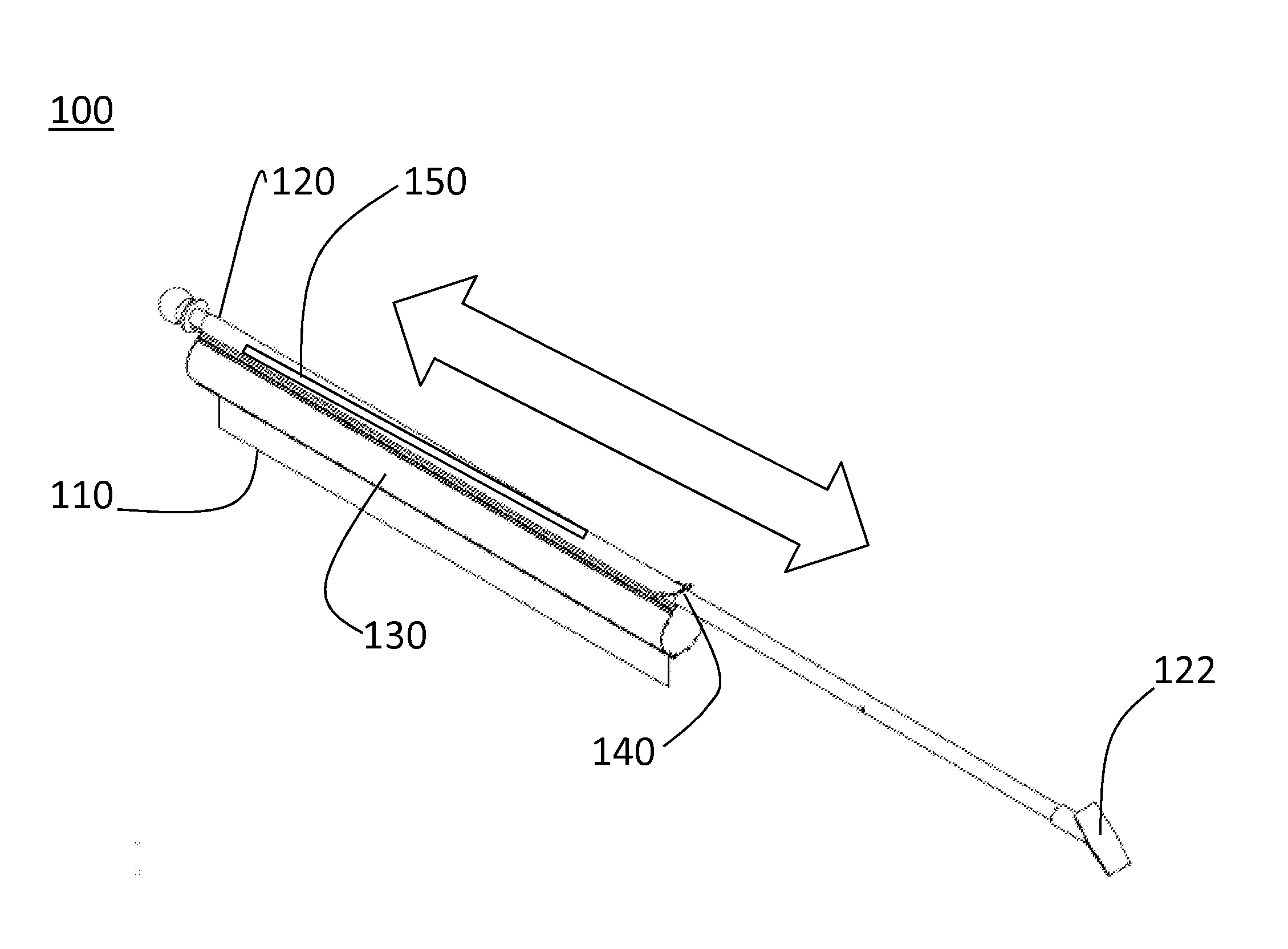
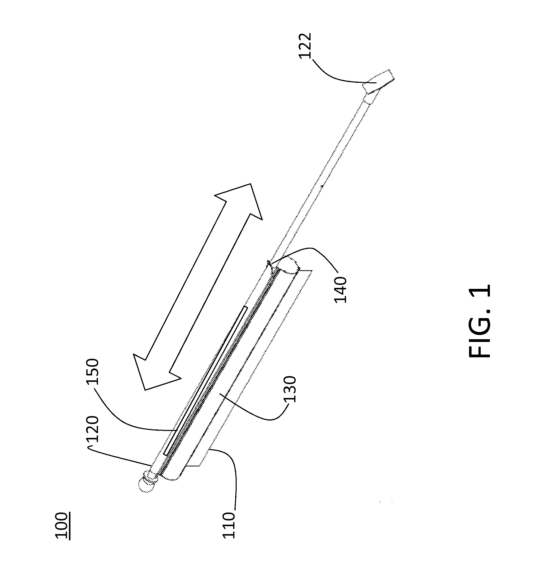
[0013]FIG. 1 depicts a system 100 to display a flag 110 according to an embodiment of the invention. The attachment member 120 affixes the system 100 to a structure (not shown) such as, for example, a building or a ground mount. The attachment portion 122 of the attachment member 120 may pivot in various embodiments to allow attachment of the system 100 at various angles against the structure. For example, a typical arrangement is one in which the system 100 is attached at the attachment portion 122 such that the flag 110 is flying at a forty-five degree angle. The attachment member 120 in the embodiment of FIG. 1 is essentially a rod with a base (attachment portion 122) that serves as the point at which the attachment member 120 is affixed to the structure. Exemplary types of fasteners to affix the attachment member 120 to a building or other structure include screws, nails, and adhesives. The attachment member 120 is coupled to a flag housing 130 that houses the flag 110.

[0014]The...


PUM

PropertyMeasurementUnit
Weightaaaaaaaaaa
Shapeaaaaaaaaaa

Abstract

A system to display a flag and a method of manufacturing the flag display system are described. The system includes an attachment member configured to affix the system to a structure horizontally, vertically, or at an angle in between. The system also includes a flag housing configured to house a flag, the flag housing being coupled to the attachment member, a roller member disposed in the flag housing, the flag being disposed to roll onto and off of the roller member to be stored or displayed, respectively, and a guide member coupled to the roller member at a first end in the flag housing, the guide member being configured to maintain alignment between the flag and the roller member when the flag is rolled onto and off of the roller member.

Description

CROSS-REFERENCE TO RELATED APPLICATION[0001]This application claims priority to Provisional Patent Application Ser. No.: 61 / 560,027 filed Nov. 15, 2011, the disclosure of which is incorporated by reference herein in its entirety.BACKGROUND OF THE INVENTION[0002]The subject matter disclosed herein relates to displaying a flag.[0003]Individuals and businesses display flags on a regular basis. Typically, flags are displayed on vertical masts or ones that make a forty-five degree angle with a vertical structure, such as an exterior wall of a home. When flags are left outdoors during weather conditions such as rain, heavy winds, and dust storms, the condition of the flag material can deteriorate. Preventing this deterioration has required frequent and inconvenient removal and resetting. Thus, a convenient and effective way to display a flag over a long period of time would be appreciated.BRIEF DESCRIPTION OF THE INVENTION[0004]According to an aspect, a system to display a flag includes a...

Claims


Application Information

Patent Timeline
IPC IPC(8): G09F11/18H05K13/04B23P11/00
CPCG09F11/21Y10T29/49826Y10T29/49117G09F11/30
Inventor SCATURRO, ANTHONYDONOHUE, PAULMEPPLELINK, RANDYDAUGHERTY, DAVID
Owner CJ LTD LLC
Why Eureka
Try Eureka